�A/C COMPRESSOR SERVICING
�1993 Nissan Sentra
1993 AIR CONDITIONING & HEAT Compressor Servicing
READ THIS FIRST
| NOTE: | The purpose of this article is to provide GENERAL servicing overview. For more specific information, refer to the AUTO A/C-HEAT SYSTEM, MANUAL A/C-HEAT SYSTEM, or HEATER SYSTEM articles in this section. |
| NOTE: | Due to variety of clutch and shaft seal configurations, obtain appropriate A/C compressor service tools for compressor being serviced. |
ATSUGI ROTARY VANE CLUTCH COIL R & I
Removal
When replacing compressor clutch, be careful not to scratch shaft or bend pulley. When removing center bolt, hold clutch disc with Clutch Holder (KV99231010). Using Hub Puller (KV998VR001), remove clutch disc. When removing pulley, remove lock nut with Hub Socket (KV99235160).
Installation
1) Tighten center bolt to 81-104 INCH lbs. (9.1-11.8 N.m). Tighten lock nut to 21-29 ft. lbs. (29-39 N.m). Using feeler gauge, ensure clearance between clutch disc and pulley is .012-.024" (.30-.60 mm).
2) If clearance is not correct, replace adjustment shim(s). See Fig. 1. Break-in clutch by engaging and disengaging clutch about 30 times.
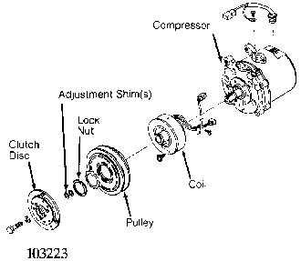
Fig. 1: Exploded View Of Compressor (Atsugi Rotary Vane) Courtesy of Nissan Motor Co., U.S.A.
BOSCH 6-CYLINDER CLUTCH COIL R & I
Removal
1) Hold clutch plate and remove shaft nut. Using Clutch Plate Remover (64 5 00), remove clutch plate. Using snap ring pliers, remove circlip and remove pulley assembly.
2) If pulley bearing is being replaced, remove circlip at rear of pulley. Press bearing and spacer from pulley. Press in new bearing with spacer and replace circlip.
Installation
1) Clean all surfaces. Install pulley assembly on compressor and install circlip. Ensure clutch plate shim is in place on shaft. Install clutch plate and nut. Tighten nut to 13-15 ft. lbs. (18-20 N. m).
2) Using a feeler gauge, check clutch plate-to-pulley clearance. Clearance should be .028-.051" (.7-1.3 mm). If clearance is not correct, remove clutch plate and replace clutch plate shim. See Fig. 2.
BOSCH 6-CYLINDER SHAFT SEAL R & I
Removal
Remove clutch plate. Remove shaft key and circlip. Using Seal Seat Remover/Installer (64 5 030), remove seal seat. Using Seal Remover/Installer (64 5 040), turn seal slightly clockwise to disengage tangs and pull out shaft seal. Remove "O" ring seal.
Installation
1) Coat new "O" ring seal with refrigerant oil and install. Coat new shaft seal with refrigerant oil and install seal on Seal Remover/Installer(64 5 040). Ensure shaft seal and shaft machine surfaces align. Insert shaft seal and turn slightly counterclockwise to secure on shaft.
2) Using sleeve from Seal Seat Remover/Installer (64 5 030), push seal seat into compressor and install circlip. Install shaft key and clutch plate. Check compressor oil level before charging system.
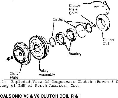
Fig. 2: Exploded View Of Compressor Clutch (Bosch 6-Cylinder) Courtesy of BMW of North America, Inc.
NOTE: Calsonic V6 compressor servicing procedure is not available from manufacturer.
Removal
1) Remove shaft nut while holding clutch plate with Clutch Disc Wrench (J-39072). Install clutch disc Puller Set (J-39073-4, J33013-1, J-33013-3) and remove clutch plate.
2) Remove snap ring. Use a universal gear puller to remove clutch pulley. See Fig. 3. Remove screw from clutch coil lead. Use puller to remove clutch coil.
Installation
1) To install clutch coil, reverse removal procedure. Ensure coil lead is installed in original position. Using puller set and Coil Jig (J-39073-1), carefully press clutch coil into place.
2) Install a new clutch pulley snap ring, being careful not to damage shaft seal. Press clutch plate into place. Install shaft nut and torque to 89-106 INCH lbs. (10-12 N.m).
3) Use a feeler gauge to check clutch plate-to-pulley clearance. Clearance should be .012-.024" (.30-.60 mm). If clearance is too large, remove shaft nut and again press in clutch plate. If clearance is too small, increase gap by pulling up clutch plate. DO NOT remove shaft nut.
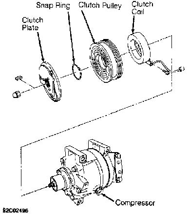
Fig. 3: Exploded View Of Compressor Clutch (Calsonic V5) Courtesy of Nissan Motor Co., U.S.A.
DIESEL KIKI ROTARY VANE CLUTCH COIL R & I
Removal
1) Hold clutch disc using Clutch Holder (J-33939) and remove center bolt. Using Puller (J-33944-A) and Forcing Bolt (J-33944-4), remove clutch disc. Remove adjustment shim(s) and snap ring.
2) Remove pulley using Pilot (J-38424) and universal puller. Remove coil lead screw, clutch coil screws and coil. Remove snap ring and bearing if necessary.
Installation
1) Ensure coil lead is installed in original position. Install and tighten coil screws to 35-53 INCH lbs. (4-6 N.m). Press pulley onto compressor using Pulley Installer (J-33940). Install snap ring and adjustment shim(s).
2) Install clutch disc and tighten center bolt to 106-133 INCH lbs. (12-15 N.m). Using feeler gauge, ensure clearance between clutch disc and pulley is .012-.024" (.30-.60 mm). If clearance is incorrect, add or remove shim(s) as necessary. Break-in clutch by engaging and disengaging clutch 30 times.
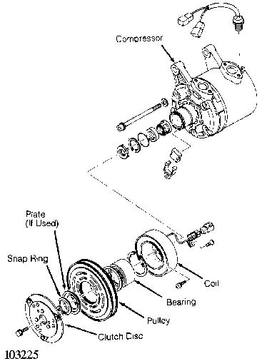
Fig. 4: Exploded View Of Compressor (Diesel Kiki Rotary Vane) Courtesy of Nissan Motor Co., U.S.A.
DIESEL KIKI 6-CYLINDER CLUTCH COIL R & I
NOTE: Due to variety of clutch and shaft seal configurations,
obtain appropriate A/C compressor service tools for
compressor being serviced.
Removal & Installation
1) Using Clutch Holder (J-33939) to prevent clutch disc from rotating, remove shaft bolt. Using Clutch Disc Puller (J-33944-A) and Forcing Bolt (J-33944-4), remove clutch disc. Remove shim(s) from compressor drive shaft or clutch disc. See Fig. 5.
2) Remove snap ring, cover and pulley. With Puller Guide (J33943-A) in center of pulley, attach Crossbar (J-8433) to outside diameter of pulley. Tighten crossbar bolt against puller guide to remove pulley. Remove coil lead, screws, and coil.
3) To install, reverse removal procedure. Install cover snap ring with beveled side facing out. Install clutch disc and tighten center bolt to 133 INCH lbs. (15 N.m).
4) Using feeler gauge, ensure clearance between clutch disc and pulley is .012-.024" (.30-.60 mm). If clearance is incorrect, add or remove shim(s) as necessary.
DIESEL KIKI SHAFT SEAL R & I
Removal & Installation
1) Remove clutch coil. Remove and discard felt. Using Shaft Seal Cover Remover/Installer (J-33942), push down and turn remover clockwise to engage tangs to cover. Slowly remove seal cover from bore.
2) Remove shaft seal snap ring. Use Shaft Seal Remover (J33942-B) to remove seal. Remove compressor through bolts, front head and "O" ring. If necessary, replace front and rear valve plates, reed valves, and "O" rings.
3) To install, reverse removal procedure. Coat "O" ring, shaft seal and seal seat with refrigerant oil. Place Shaft Seal Guide (J-34614) over end of compressor shaft. Ensure chamfered portion of shaft seal retainer aligns with chamfered portion on compressor shaft.
4) Install front head and tighten compressor through bolts, in a crisscross pattern, to 16 ft. lbs. (22 N.m). Install shaft seal cover and felt. See Fig. 5. Rotate compressor drive shaft 2-3 times to ensure compressor operates smoothly.
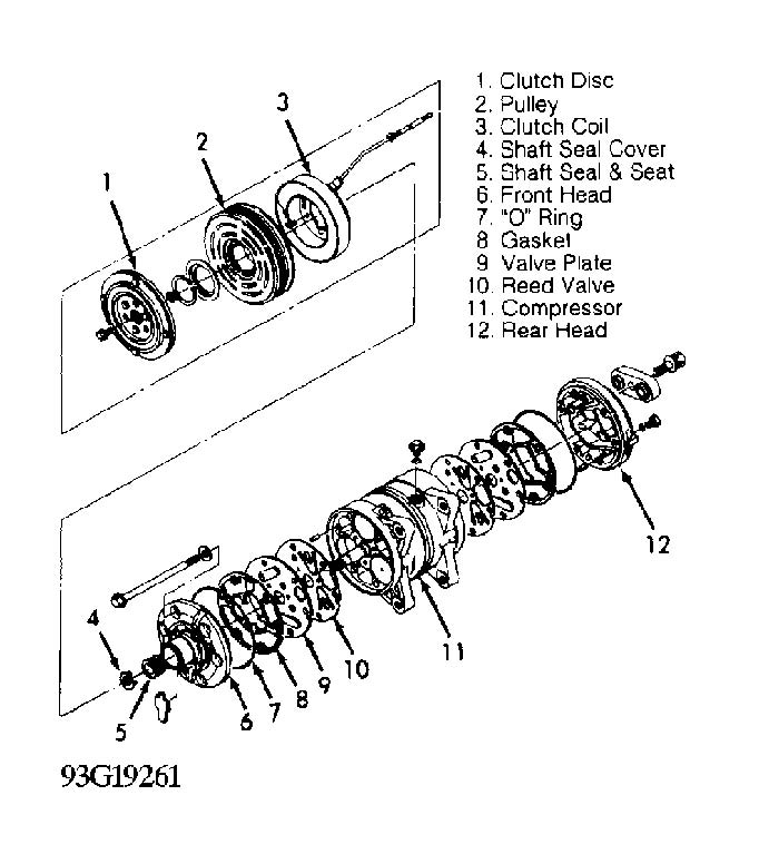
Fig. 5: Exploded View Of Compressor (Diesel Kiki 6-Cylinder) Courtesy of Isuzu Motor Co.
FORD FX-15 CLUTCH COIL R & I
Removal
1) Using Clutch Holder (000 41 0812 05), remove clutch plate bolt. Using an 8-mm bolt threaded into clutch plate, remove clutch plate and shim(s). See Fig. 6.
2) Remove snap ring and pulley assembly. Install Shaft Protector (49 UN01 047) over shaft seal opening. Use a 2-jaw puller to remove clutch coil from compressor.
Installation
1) Ensure clutch coil mounting surface is clean. Use Coil Installer (49 UN01 046) and 2-jaw puller engaged to rear side of compressor front mounts to press coil into place.
2) Install pulley assembly. Install pulley assembly snap ring with bevel side of snap ring facing out. Install shim(s) and clutch plate. Install a new clutch plate bolt and tighten to 97-115 INCH lbs. (11-13 N.m).
3) Use a feeler gauge to check clearance between clutch plate and pulley assembly. Clearance should be .018-.033" (.46-.84 mm). If clearance is incorrect, add or remove shims as necessary.
FORD FX-15 SHAFT SEAL R & I
Removal
1) Using Clutch Holder (000 41 0812 05), remove clutch plate bolt. Using an 8-mm bolt threaded into clutch plate, remove clutch plate and shim(s). See Fig. 6.
2) Remove shaft felt seal. Thoroughly clean seal area of compressor. Remove shaft seal snap ring. Position Shaft Seal Remover (49 UN01 044) over compressor shaft.
3) Push shaft seal remover downward against seal. Ensure end of shaft seal remover is engaged with inside of seal. Rotate shaft seal remover clockwise to expand remover tip inside seal. Pull shaft seal from compressor.
Installation
1) Lubricate shaft seal protector and shaft seal with refrigerant oil. Install shaft seal on shaft seal protector so lip seal is toward compressor (large end of shaft seal protector).
2) Install shaft seal protector on compressor shaft. Using Shaft Seal Installer (49 UN01 043), push shaft seal down seal protector until seal is seated.
3) Remove shaft seal installer and protector. Install a new shaft seal retaining snap ring and shaft seal felt. Install shim(s) and clutch plate. Install a new clutch plate retaining bolt and tighten to 97-115 INCH lbs. (11-13 N.m).
4) Use a feeler gauge to check clearance between clutch plate and pulley assembly. Clearance should be .018-.033" (.46-.84 mm). If clearance is incorrect, add or remove shims as necessary.
Fig. 6: Exploded View Of Compressor Clutch (Ford FX-15) Courtesy of Mazda Motors Corp.
HADSYS 7-CYLINDER CLUTCH COIL R & I
Removal
Using Clutch Holder (J-37872), hold pressure plate and remove shaft bolt. Remove pressure plate and adjustment shim(s). See Fig. 7. Remove snap ring. Using universal puller, remove compressor pulley. Remove clutch coil.
Installation
Install clutch coil in reverse order of removal. Ensure snap ring is properly seated. Apply locking compound to shaft bolt and tighten it to 62 INCH lbs. (7 N.m). Ensure clearance between pressure plate and pulley is 0.012-0.024" (.30-.60 mm). If clearance is incorrect, add or remove shim(s) as necessary.

Fig. 7: Exploded View Of Compressor (Hadsys 7-Cylinder) Courtesy of American Honda Motor Co., Inc.
Removal
1) Clamp Holding Fixture (J-25008-A) in vise. Attach compressor to holding fixture. Use Clutch Hub Holder (J-33027) to hold clutch and remove shaft nut.
2) Thread Hub and Drive Plate Assembly Remover/Installer (J37707) into hub. Hold body of remover with wrench and turn center bolt into remover body to remove clutch plate and hub assembly. Remove shaft key and save for installation.
3) Remove snap ring. Place Puller Guide (J-25031-1) in center of pulley housing. Engage universal puller to outer diameter of pulley (clutch rotor). See Fig. 8. Hold puller and tighten screw to remove pulley.
4) Invert pulley and place on work bench. Press out rotor bearing using handle and Bearing Remover (J-9398-A). Attach universal puller to outside diameter of clutch coil. Tighten bolt against puller guide to remove clutch coil.
CAUTION: DO NOT drive or pound on clutch hub or shaft.
Installation
1) Ensure clutch coil is installed in original position. Press pulley onto compressor using Installer (J-9481-A) and handle. Install shaft key into hub key groove. Allow key to project approximately 3/16" (4.8 mm) out of keyway.
2) Ensure frictional surface of clutch plate and clutch rotor are clean before installing clutch plate and hub assembly. Align shaft key with shaft keyway and place clutch plate and hub assembly onto compressor shaft.
3) Hold hub and drive plate remover/installer with wrench and tighten nut to press hub into shaft until there is a .020-.040" (.5-1. 0 mm) air gap between plate and clutch rotor. Install a new shaft nut and tighten to 10 ft. lbs. (14 N.m). Ensure rotor is not rubbing on clutch plate.
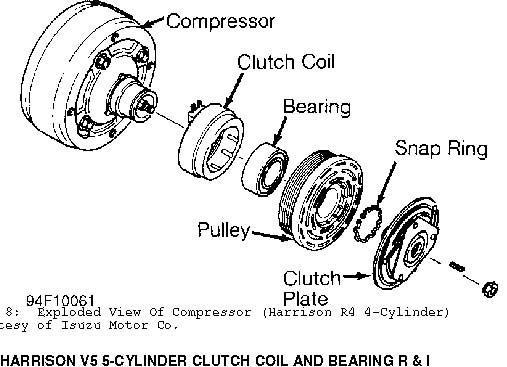
Fig. 8: Exploded View Of Compressor (Harrison R4 4-Cylinder) Courtesy of Isuzu Motor Co.
Removal
1) Clamp Holding Fixture (J-34992) in vise. Attach compressor to holding fixture. Use Clutch Hub Holder (J-33027-A) to hold clutch. Remove shaft nut using Socket (J-33022). See Fig. 9.
2) Thread Clutch Plate and Hub Assembly Remover (J-33013-B) into hub. Hold body of remover with wrench and turn center bolt to remove clutch plate and hub assembly. Remove snap ring. Remove shaft key and save for installation.
3) Place Puller Guide (J-33023-A) in center of pulley housing. Engage Rotor/Bearing Puller (J-33020) to inner circle of slots in pulley (rotor). Hold rotor/bearing puller in place and tighten screw to remove pulley.
4) Remove screw from rotor/bearing puller. Invert assembly and place on work bench with rotor/bearing puller still engaged. Remove hub bearing using handle and Bearing Remover (J-9398-A).
5) With puller guide in place, attach Crossbar (J-8433-1) and Puller (J-33025) to outside diameter of clutch coil. Tighten crossbar Bolt (J-8433-3) against puller guide to remove clutch coil.
Installation
1) Ensure clutch coil is installed in original position. Press coil into position using crossbar, clutch Coil Installer (J33024) and Through Bolts (J-34992-2). Stake compressor housing 120 degrees apart to secure coil.
2) Position Rotor/Bearing Installer (J-33017) and puller guide over inner race of bearing. Using through bolts, assemble crossbar over puller pilot and tighten through bolts onto holding fixture. Tighten crossbar bolt to press pulley/bearing assembly onto compressor.
3) Install shaft key into hub key groove. Allow key to project approximately 1/8" (3.2 mm) out of keyway. Align shaft key with shaft keyway and place clutch plate and hub assembly onto compressor shaft.
CAUTION: Do not drive or pound on clutch hub or compressor shaft, as compressor could be damaged internally.
4) Hold hex portion of Hub Installer (J-33013) with a wrench. Tighten center screw to press hub into shaft until there is .020-.030" (.50-.76 mm) air gap between frictional plate and clutch rotor.
5) Install new shaft nut with small diameter boss of nut against crankshaft shoulder. Use Socket (J-33022) and Clutch Hub Holder (J-33027-A). Tighten shaft nut to 12 ft. lbs. (16 N.m). Ensure pulley does not rub on clutch plate. See Fig. 9.
HARRISON V5 5-CYLINDER SHAFT SEAL R & I
Removal
Remove clutch plate and hub assembly. Remove shaft seal snap ring. Thoroughly clean inside of compressor neck area around shaft and seal. Engage tangs of Seal Remover/Installer (J-23128-A) into recessed portion of seal and remove seal. Remove and discard "O" ring from compressor neck. Thoroughly clean inside of compressor neck and "O" ring groove.
Installation
1) Coat new "O" ring with refrigerant oil and install on "O" Ring Installer (J-33011). Install "O" ring into groove in compressor neck. Attach new seal to seal remover/installer. Dip shaft seal in clean refrigerant oil.
2) Place Seal Protector (J-34614) over compressor shaft. Push
new seal over shaft protector. Install new seal snap ring with flat side against seal. Install clutch plate assembly.
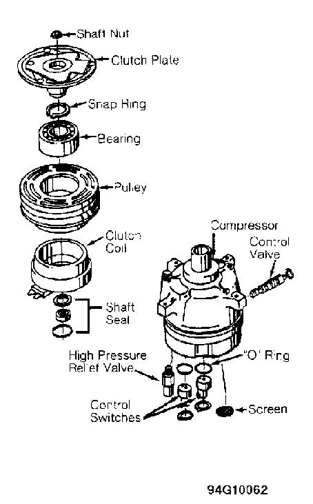
Fig. 9: Exploded View Of Compressor (Harrison V5 5-Cylinder) Courtesy of General Motors Corp.
HITACHI 6-CYLINDER CLUTCH COIL AND SEAL R & I
Removal
1) Hold clutch hub with Clutch Tightener (925770000). Remove shaft nut from shaft. Using Clutch Hub Remover (926130000), remove clutch hub. Use snap ring pliers to remove inner snap ring.
2) Remove pulley and bearing assembly. Remove screws securing clutch coil lead. Remove inner snap ring from clutch coil. Remove clutch coil from front cover.
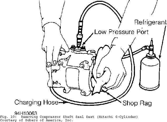
3) Remove shaft key. Use snap ring pliers to remove shaft seal snap ring. Wrap a rag around compressor shaft. Using Injector Needle (92619000) and refrigerant can, slowly pressurize compressor at low pressure (suction) service port. See Fig. 10. Catch shaft seal seat in rag.
4) Insert Shaft Seal Remover/Installer (926120000) through open end of front cover. Slowly pull out remover/installer to remove shaft seal.
Installation
1) Ensure shaft seal contact surface is free of dirt. Lubricate with refrigerant oil. Using shaft seal remover/installer, insert shaft seal.
2) To install clutch coil and hub, reverse removal procedure. Tighten shaft nut to 14-15 ft. lbs. (19-21 N.m). Ensure clearance between pressure plate and pulley is 0.020-0.031" (.50-.80 mm).
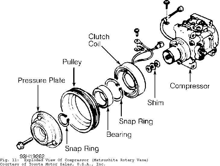
MATSUSHITA ROTARY VANE CLUTCH COIL R & I
Removal & Installation
1) Using Pressure Plate Holder (J-7624) and socket, remove center bolt. Thread Puller (J-34878) onto pressure plate. Hold pressure plate with pressure plate holder and tighten puller to remove pressure plate.
2) Remove shim(s) from shaft. Remove snap ring and, using a plastic hammer, tap pulley off. Remove screw for clutch coil lead. Remove snap ring and clutch coil. See Fig. 11.
3) To install, reverse removal procedure. Tighten shaft bolt to 10 ft. lbs (14 N.m). Using feeler gauge, ensure clearance between pressure plate and pulley is .014-.026" (.35-.65 mm). If clearance is incorrect, add or remove shim(s) as necessary.
NIPPONDENSO TV12 ROTARY VANE CLUTCH COIL R & I
Removal
1) Hold clutch disc with Clutch Holder (00007-10331) and remove shaft nut. Install Clutch Disc Remover (4992-02-020) and remove clutch disc and shims. See Fig. 12.
2) Remove pulley snap ring and tap pulley (with bearing) off of compressor with plastic hammer. Remove screw for clutch coil lead. Remove snap ring and clutch coil.
Installation
To install, reverse removal procedure. Ensure pulley-toclutch disc clearance is .016-.024" (.40-.60 mm). If clearance is incorrect, add or remove shim(s) as necessary.
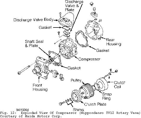
NIPPONDENSO TV12 DISCHARGE VALVE & SHAFT SEAL R & I
Removal
1) Drain and measure compressor oil in compressor. Remove discharge valve body through bolts. Remove discharge valve body bolts and body. Remove discharge valve plate and discharge valve.
2) Remove compressor through bolts and front and rear housing (oil separator case). Remove pins and gaskets. Remove shaft seal from shaft. Press shaft seal plate off of front housing (head cover).
Installation
To install components, reverse removal procedure. Tighten compressor through bolts to 19 ft. lbs. (26 N.m). Tighten discharge valve bolts to 41 INCH lbs. (4.6 N.m). Tighten discharge valve body and body through bolts to 96 INCH lbs. (10.8 N.m).
NIPPONDENSO 6 & 10-CYLINDER CLUTCH COIL AND BEARING R & I
NOTE: Due to variety of clutch and shaft seal configurations,
obtain appropriate A/C compressor service tools for
compressor being serviced.
Removal
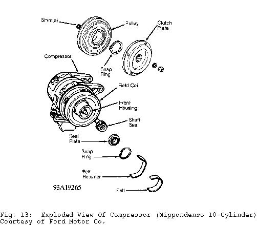
1) Hold clutch plate stationary and remove shaft bolt (or nut). Remove clutch plate using puller. Remove shim(s) from shaft and snap ring. Tap pulley off shaft with plastic hammer. If pulley cannot be removed by hand, use commercially available puller.
2) Remove snap ring, bearing, and seal (if equipped) from pulley. See Fig. 13. Remove screw for clutch coil lead. Remove snap ring and clutch coil.
Installation
To install, reverse removal procedure. Ensure snap rings are installed with beveled side facing out. Tighten shaft bolt (or nut) to 13-14 ft. lbs. (17-19 N.m) on Fox, MR2 and Scoupe; 10-13 ft. lbs. (1417 N.m) on all others. Ensure air gap between clutch plate and pulley is .024-.040" (.60-1.00 mm) on Fox and MR2; .014-.026" (.36-.66 mm) on all others. If air gap is incorrect, add or remove shim(s) as necessary.
NOTE: To check air gap, place a dial indicator on clutch plate.
Apply voltage to clutch coil. Check air gap between clutch
plate and drive pulley. Ensure air gap is as specified.
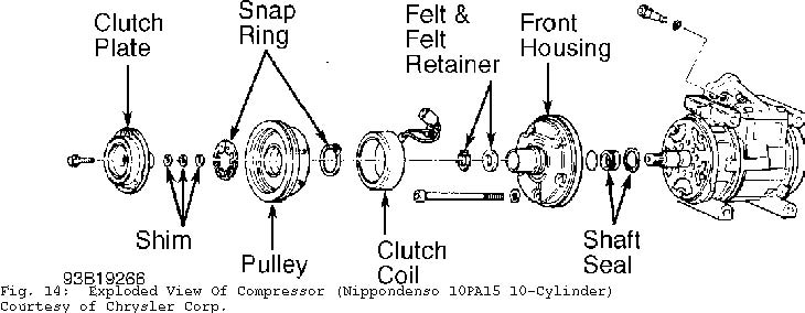
NIPPONDENSO 6 & 10-CYLINDER SHAFT SEAL R & I
NOTE: On Chrysler and Mitsubishi, remove compressor through bolts
and front housing to remove shaft seal. See Fig. 14.
Alternately tighten through bolts to 18-21 ft. lbs. (24-28
N.m).
Removal
1) Remove clutch plate and pulley. Remove shim(s) from shaft. Remove clutch coil if necessary. Remove felt and felt retainer (if equipped). Place shaft key remover on shaft and turn to remove key.
2) Remove seal plate snap ring. Engage plate remover on seal plate and pull up to remove seal plate. Engage shaft seal remover/installer to shaft seal and pull up to remove shaft seal from front housing.
Installation
1) Apply clean refrigerant oil to compressor housing bore. Lubricate shaft seal with refrigerant oil and install in front housing. Lubricate seal plate and install in front housing.
2) Install shaft key, snap ring, felt retainer and felt. With clutch plate installed, ensure air gap between clutch plate and pulley is .024-.040" (.60-1.00 mm) on Fox and MR2; .014-.026" (.36-.66 mm) on all others. If air gap is incorrect, add or remove shim(s) as necessary.
PANASONIC ROTARY VANE CLUTCH COIL R & I
Removal
Hold clutch disc stationary and remove shaft bolt. Remove clutch disc and shim(s) from shaft. Remove snap ring. Using a puller, remove pulley. Remove screw from clutch coil lead. Remove screws and field coil.
Installation
To install, reverse removal procedure. Tighten field coil screws to 30-57 INCH lbs. (3.4-6.4 N.m). Ensure pulley-to-armature gap is .016-.020" (.40-.50 mm). If air gap is incorrect, add or remove shim(s) as necessary. Tighten shaft bolt to 97-115 INCH lbs. (11-13 N. m).
PANASONIC ROTARY VANE DISCHARGE VALVE R & I
Removal & Installation
Remove compressor head cover. Remove discharge valve stopper and discharge valve. See Fig. 15. Install replacement discharge valve and stopper, reversing removal procedure. Tighten discharge valve bolts to 27-34 INCH lbs. (3.0-3.8 N.m). Tighten compressor head cover bolts to 89 INCH lbs. (10 N.m).
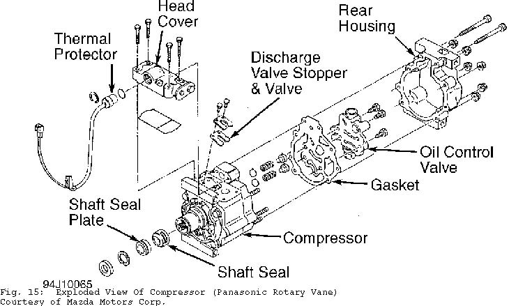
PANASONIC ROTARY VANE OIL CONTROL VALVE R & I
Removal & Installation
Remove compressor rear cover. Remove oil control valve. Remove springs, valve, and rear cover seal. To install components, reverse removal procedure. Tighten oil control valve bolts to 89 INCH lbs. (10 N.m). Tighten rear cover nuts to 21 ft. lbs. (29 N.m) and bolts to 89 INCH lbs. (10 N.m).
PANASONIC ROTARY VANE SHAFT SEAL R & I
Removal & Installation
Remove clutch disc and shim(s). Remove felt seal and snap ring. Using Seal Plate Remover (49 B061 005), engage and remove shaft seal plate. Remove shaft seal with Seal Remover/Installer (49 B061 006). To install, reverse removal procedure. Coat new seal plate and seal with clean refrigerant oil. DO NOT touch seal surfaces with fingers.
SANDEN SCROLL CLUTCH COIL AND SHAFT SEAL R & I
NOTE: Due to variety of clutch and shaft seal configurations,
obtain appropriate A/C compressor service tools for
compressor being serviced.
Removal (Chrysler & Mitsubishi Except Galant & Mirage)
1) Remove drive belt pulley (if equipped). Hold clutch plate using Pliers (MB991367) and Bolts (MB991386). Use a ratchet and socket to remove clutch hub nut.
2) Remove clutch plate. Remove snap ring with internal snap ring pliers. Remove clutch hub (rotor). Remove snap ring and clutch coil.
3) Using an awl, remove bearing cover and retainer. Using Bearing Remover (MB991456), engage bearing grooves. Place base of bearing remover over remover arms and tighten nut.
4) Tighten bearing remover bolt to withdraw bearing from compressor. Engage grooves of Shaft Seal Remover/Installer (MB991458) and pull straight up on shaft seal.
Installation (Chrysler & Mitsubishi Except Galant & Mirage)
1) To install shaft seal, ensure front housing is free of foreign objects. Lubricate Shaft Seal Protector (MB991459) and place over compressor shaft. Lubricate shaft seal and install using shaft seal remover/installer. Remove shaft seal protector.
2) Using a 21 mm socket or Drift (MB991301), carefully press bearing onto compressor shaft. Install clutch coil so that alignment pin is engaged. Install clutch coil snap ring with tapered side facing out.
3) Align armature plate with crankshaft spline. Tighten shaft nut to 12 ft. lbs (16 N.m). Using feeler gauge, ensure clearance between pressure plate and pulley is .016-.024" (.40-0.60 mm). If clearance is incorrect, add or remove shim(s) as necessary.
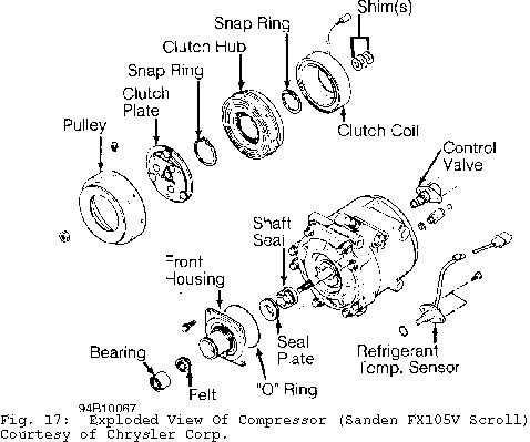
Removal (Chrysler & Mitsubishi Galant & Mirage) 1) Hold clutch plate by securing 2 box-end wrenches with two
6-mm bolts, 1" (25 mm) or longer. Holding bow-end wrenches, use a ratchet and socket to remove clutch hub nut.
2) Remove clutch plate. See Fig. 17. Remove snap ring with internal snap ring pliers. Remove clutch hub. Remove snap ring and clutch coil.
3) Remove front housing bolts. Remove front housing and "O" ring from compressor. Remove shaft seal from shaft. Remove snap ring from back side of front housing. Remove seal plate. Use brass drift and hammer to lightly tap shaft bearing from front housing. Remove felt seal.
NOTE: DO NOT touch sealing surfaces of shaft seal carbon ring and shaft seal plate.
Installation (Chrysler & Mitsubishi Galant & Mirage)
1) Lubricate shaft seal with compressor oil. Align notches on shaft seal with notches on shaft. Install shaft seal plate on front housing. Install front seal housing to compressor.
2) Use Drift (MB991301) to install felt into front housing. Ensure metal ring on felt faces up. Use drift to press bearing into front housing.
3) Align and install clutch coil. Install snap ring so tapered surface faces outward. Install clutch hub. Install snap ring. Align clutch plate mark with shaft; where there are no splines on shaft.
4) Tighten clutch hub nut to 12 ft. lbs. (16 N.m). Using feeler gauge, measure clutch plate-to-clutch hub gap. If gap is not . 012-.024" (.30-.60 mm), remove clutch assembly and add or remove shim(s).
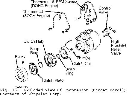
Removal & Installation (Honda & Hyundai) 1) Remove shaft nut while holding clutch plate with Armature
Holder (J-37872). Using Puller (07935-8050003), remove pressure plate and shim(s). See Fig. 16. Remove snap ring.
2) Place Seal Driver (07945-4150200) in center of pulley. Engage universal puller to outer diameter of pulley. DO NOT engage puller on belt area. Hold puller in place and tighten screw to remove pulley. Remove screw for clutch coil lead. Remove snap ring and clutch coil.
3) To install clutch coil, reverse removal procedure. Align lug on clutch coil with hole in compressor. Install snap rings with chamfered side facing out. Tighten shaft nut to 12-14 ft. lbs. (16-19 N.m). Using feeler gauge, ensure clearance between pressure plate and pulley is .014-.026" (.35-.65 mm). If clearance is incorrect, add or remove shim(s) as necessary.
NOTE: Shaft seal removal and installation procedures not available from Honda or Hyundai.
SANDEN 5-CYLINDER CLUTCH COIL R & I
Removal
1) Hold clutch plate, using Holder (0000-41-0809-01), and remove shaft nut. Remove clutch plate using Puller (0000-41-0809-02). Remove shaft key and shim(s). Remove external front housing snap ring and internal bearing snap ring (if used).
2) Install Clutch Pilot (0000-41-0810-77), Pulley/Clutch Remover (0000-41-0810-76), and Puller (0000-41-0804-51/57) to remove pulley assembly. Remove snap ring and drive bearing out of pulley. Remove screw for clutch coil lead. Remove snap ring and clutch coil.
Installation
1) Install new bearing, ensuring Bearing Installer (000-410804-43) contacts outer race of bearing. Install snap ring and ensure bearing turns freely.
2) Install clutch coil, ensuring lug on coil aligns with hole in front housing. Support compressor on rear mounting ears. Align rotor on front housing hub. Use bearing installer and Driver (0000-410810-59) to install pulley. With pulley seated, install snap ring(s). Install shim(s) and shaft key.
3) Place clutch plate over shaft and, using Shaft Protector (0000-41-0809-10), tap clutch plate into place. Install and tighten shaft nut to 25-32 ft. lbs. (34-44 N.m). Using feeler gauge, ensure clearance between clutch plate and pulley is .016-.032" (.40-.80 mm). If clearance is incorrect, add or remove shim(s) as necessary.
SANDEN 5-CYLINDER CYLINDER HEAD & VALVE PLATE R & I
Removal & Installation
Remove compressor cylinder head (rear cover) bolts. Carefully pry cylinder head of compressor. Remove reed valve plate and gasket. To install components, reverse removal procedure. Tighten compressor cylinder head bolts, in a crisscross pattern, to 21-29 ft. lbs. (29-39 N.m).
SANDEN 5-CYLINDER SHAFT SEAL R & I
Removal
Remove shaft nut and clutch plate. Remove shaft key and shim(s). Carefully remove felt ring. Remove shaft seal seat snap ring. Using Seal Seat Remover/Installer (0000-41-0810-73), carefully remove seal seat. Using Shaft Seal Remover/Installer (0000-41-0812-11), carefully remove shaft seal.
Installation
1) Install Seal Protector (0000-41-0812-13) over shaft. Place new seal on remover/installer. DO NOT touch carbon sealing surface with fingers. Dip seal in refrigerant oil and install. Remove seal installer by turning counterclockwise.
2) Coat seal seat with refrigerant oil. Install seal seat using remover/installer. Install seal seat snap ring (with flat side down). Install shim(s), felt ring and shaft key. Install shaft nut and clutch plate. Ensure clearance between clutch plate and pulley is . 016-.032" (.40-.80 mm). If clearance is incorrect, add or remove shim(s) as necessary.
SANDEN 7-CYLINDER CLUTCH COIL AND BEARING R & I
NOTE: Due to variety of clutch and shaft seal configurations,
obtain appropriate A/C compressor service tools for
compressor being serviced.
Removal
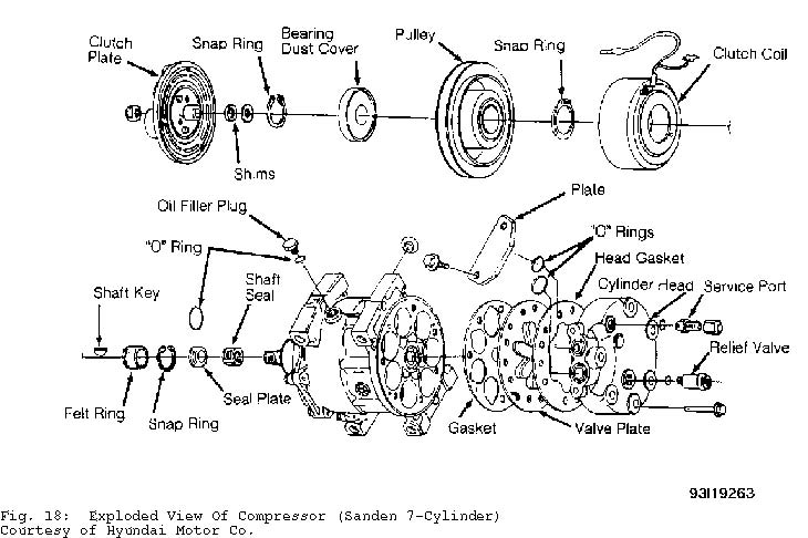
1) Install two 6-mm bolts, 1" (25 mm) or longer, in clutch plate holes. Using 2 box-end wrenches to hold bolts and to prevent clutch plate from turning, remove shaft nut.
2) Remove clutch plate using Clutch Plate Puller (0997721100). Remove clutch shim(s) and bearing dust cover. Remove external front housing snap ring. See Fig. 18.
3) Remove pulley using universal puller. Detach clutch coil lead from compressor housing. Remove clutch coil snap ring and clutch coil. If necessary, remove snap ring and bearing.
Installation
1) Align clutch coil lug with hole in compressor housing, and install clutch coil. Install clutch coil snap ring. Install drive pulley using Drive Pulley Installer (09977-21811).
2) Install external bearing snap ring. Using Seal Installer (09977-21800), install bearing dust cover. After dust cover installation, ensure there is no contact between cover and front housing.
3) Install clutch shim(s) and clutch plate. Tighten shaft nut to 13-14 ft. lbs. (17-19 N.m). Using a dial indicator, check air gap between clutch plate and drive pulley. Apply voltage to clutch coil. Ensure air gap is .016-.032" (.40-.80 mm). If clearance is incorrect, add or remove shim(s) as necessary.
NOTE: If compressor valve plate is serviced, tighten compressor cylinder head bolts to 25-26 ft. lbs. (34-35 N.m).
SANDEN 7-CYLINDER SHAFT SEAL R & I
NOTE: Check compressor refrigerant oil level when replacing seals. See COMPRESSOR OIL CHECKING article in GENERAL SERVICING.
Removal
1) Remove clutch plate, shim(s) and bearing dust cover. Tap shaft key out of slot in compressor shaft. Remove seal retainer felt ring.
2) Remove shaft seal seat snap ring. Insert Seal Seat Remover/Installer (09977-21400) into front housing and turn to engage tangs on seat. Lift seal seat out.
3) Insert Seal Remover/Installer (09977-21510) into front housing and turn to engage tangs on seal. Carefully lift shaft seal out without scratching compressor shaft.
Installation
1) Install Shaft Seal Guide Sleeve (09977-21700) over compressor shaft. Dip seal in refrigerant oil and install seal on sleeve. Using seal remover/installer, rotate seal clockwise until seal is engaged. Remove seal remover/installer by turning it counterclockwise.
2) Coat seal seat with refrigerant oil and install seal with seal seat remover/installer. Remove shaft seal guide sleeve. Install snap ring with beveled edge facing out. Install seal retainer felt
ring using seal seat remover/installer.
3) Install shaft key and clutch plate. Tighten shaft nut to 13-14 ft. lbs. (17-19 N.m). Using a dial indicator, check air gap between clutch plate and drive pulley. Apply voltage to clutch coil. Ensure air gap is .016-.032" (.40-.80 mm). If clearance is incorrect, add or remove shim(s) as necessary.
SEIKO-SEIKI ROTARY VANE
NOTE: Volvo Seiko-Seiki compressor servicing procedure is not available from manufacturer.
ZEXEL ROTARY VANE CLUTCH COIL AND BEARING R & I
Removal
1) Hold clutch disc using Clutch Disc Wrench (KV99231260) and remove center bolt. Using Clutch Disc Puller (KV99232340), remove drive plate and adjustment shim(s).
2) Remove snap ring. Remove pulley using Pilot (J-39023) and universal puller. Remove clutch coil. If necessary, remove snap ring and bearing. See Fig. 19.
Installation
1) Ensure coil lead is installed in original position. Install and tighten coil screws. Press pulley onto compressor using Pulley Installer (J-33940). Install snap ring and adjustment shim(s).
2) Install clutch disc and tighten center bolt to 11-13 ft. lbs. (15-18 N.m). Using feeler gauge, ensure clearance between clutch disc and pulley is .012-.024" (.30-.60 mm). If clearance is incorrect, add or remove shim(s) as necessary. Break-in clutch by engaging and disengaging clutch 30 times.
NOTE: Shaft seal assembly servicing procedure is not available
from manufacturer. Use exploded view as a guide. See
11-13 ft.lbs. (15-18 N.m).
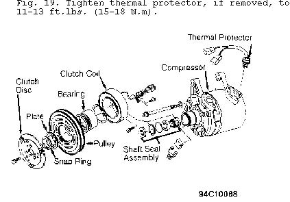
Fig. 19: Exploded View Of Compressor (Zexel Rotary Vane) Courtesy of Nissan Motor Co., U.S.A.
ZEXEL 6-CYLINDER CLUTCH COIL AND BEARING R & I
NOTE: Volvo Zexel compressor servicing procedure is not available from manufacturer.
Removal (Audi)
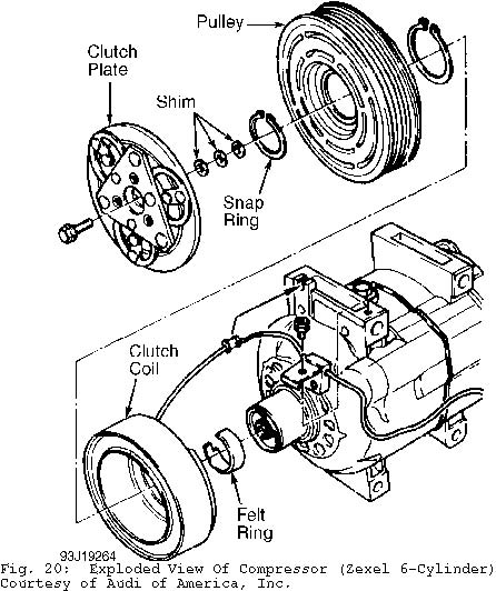
1) Using Spanner Wrench (44-4), hold clutch hub stationary and remove shaft bolt. Remove clutch plate and shim(s) using Puller (VAG 1719) and Spanner Wrench (3212). See Fig. 20. Remove snap ring.
2) Place Spacer (VAG 1719/1) in center of pulley cavity. Attach Puller (US 1078) to outer diameter of pulley and remove pulley. Remove snap ring, bearing, and clutch coil as necessary.
Installation (Audi)
Ensure clutch coil lug fits into hole on compressor housing. Using Installer (VAG 1719/2), press on pulley and install snap ring. Install shim(s) and clutch plate. Tighten shaft bolt to 11 ft. lbs. (15 N.m). Using feeler gauge, ensure air gap between pulley and clutch disc is .012-.024" (.30-.60 mm). If clearance is incorrect, add or remove shim(s) as necessary.
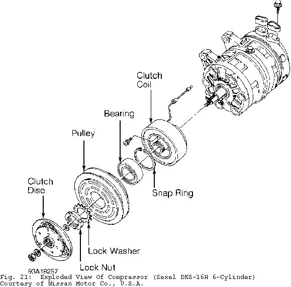
Removal (Nissan) 1) Using Clutch Disc Wrench (J-37877), hold clutch hub
stationary and remove shaft nut. Remove adjustment shim(s) and clutch disc using Clutch Disc Puller (J-26571-A).
2) Bend lock washer away from lock nut. See Fig. 21. Remove lock nut with Wrench (J-37882). Remove pulley by hand or, if difficult to remove, use Pilot (J-26720-A) and universal puller. Remove snap ring, bearing, and clutch coil as necessary.
Installation (Nissan)
1) Ensure key is installed in compressor shaft keyway. Install pulley, lock washer and pulley. Tighten lock nut to 25-29 ft. lbs. (34-39 N.m). Bend lock washer against lock nut.
2) Install clutch disc and tighten shaft nut to 10-12 ft. lbs (14-16 N.m). Using feeler gauge, ensure air gap between pulley and clutch disc is .012-.024" (.30-.60 mm). If clearance is incorrect, add or remove shim(s) as necessary. Break-in compressor clutch assembly by engaging and disengaging clutch 30 times.