�A/C-HEATER SYSTEM -MANUAL
�1993 Nissan Sentra
1993 Manual A/C-Heater Systems NX & Sentra
SPECIFICATIONS
SPECIFICATIONS TABLE
�����������������������������������������������������������������������������������������������������������������������
| Application | Specification | |
| Compressor Type | ................ Zexel DKV-14C Rotary Vane | |
| Compressor Belt Deflection | ||
New Belt ........................... 9/32-5/16" (7-8 mm)
Used Belt .......................... 9/32-5/16" (7-8 mm) System Oil Capacity ............................. 6.8 ozs. Refrigerant (R-12) Capacity ................... 23-26 ozs. System Operating Pressures (1)
High Side ................ 118-166 psi (8.3-11.7 kg/cm � )
Low Side .................... 27-37 psi (1.9-2.6 kg/cm � )
(1) - Measured at ambient temperature of about 77 � F (25 � C), with 50-70 percent relative humidity.
�����������������������������������������������������������������������������������������������������������������������
WARNING: To avoid injury from accidental air bag deployment, read and
carefully follow all SERVICE PRECAUTIONS and DISABLING &
ACTIVATING AIR BAG SYSTEM procedures in appropriate
AIR BAG RESTRAINT SYSTEM article in ACCESSORIES & ELECTRICAL
section.
DESCRIPTION
A separate evaporator housing assembly is combined with a standard heater core assembly to create an integrated A/C-heating unit. Blower motor directs airflow through evaporator and then heater core, to ducting and outlets.
OPERATION
CONTROL PANEL
Fan speed is controlled by a dial knob or a slide lever. See Fig. 1. Desired air control mode is achieved by push buttons or lever- type controls on A/C-heater control panel. A/C switch and fan controls are independent of mode controls. Slide lever controls temperature setting, and A/C button controls air conditioner operation. Sliding intake lever to the left or pressing air recirculation button will stop fresh air intake and recirculate inside air.
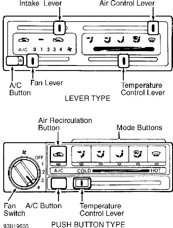
Fig. 1: Identifying A/C-Heater Control Panel Courtesy of Nissan Motor Co., U.S.A.
FUSIBLE PLUG
Fusible plug, mounted on receiver-drier, is a high temperature relief valve. When temperature is 221 � F (105 � C), plug melts to vent refrigerant to atmosphere, thereby protecting the system.
FAST IDLE CONTROL DEVICE (FICD)
When A/C system is energized, the engine control module signals FICD to adjust Auxiliary Air Control (AAC) valve to by-pass additional air and increase idle speed. This higher idle speed allows engine to idle smoothly during compressor operation.
DUAL-PRESSURE SWITCH
The dual-pressure switch is mounted on receiver-drier. See Fig. 2. Dual-pressure switch protects A/C system from high pressure build-up due to restriction, overcharge or compressor malfunction. If excessively low or high system pressure is sensed, the switch stops compressor clutch operation.
HIGH PRESSURE RELIEF VALVE
A high pressure relief valve is located on end of high pressure hose, near A/C compressor. When high pressure of 540 psi (38 kg/cm � ) is sensed, relief valve opens, venting refrigerant to atmosphere.
THERMO CONTROL AMPLIFIER
An electrical thermo control amplifier is mounted on evaporator housing. See Fig. 3. A temperature sensor (thermistor), inside evaporator housing, senses air temperature and sends signal to thermo control amplifier. Thermo control amplifier then cycles compressor clutch on and off according to temperature setting on control panel.
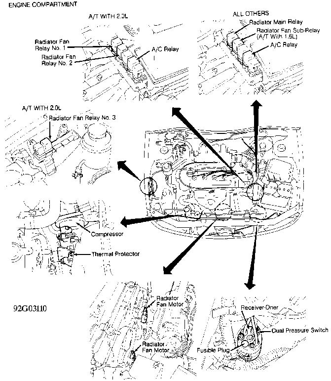
Fig. 2: Locating System Electrical Components (Engine Compartment) Courtesy of Nissan Motor Co., U.S.A.
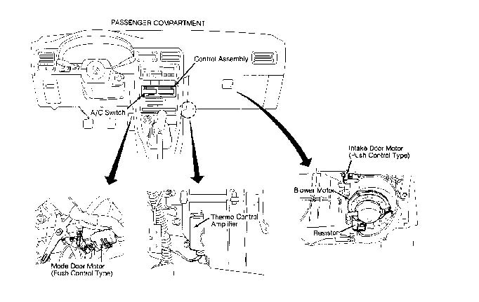
Fig. 3: Locating System Electrical Components (Passenger Compartment) Courtesy of Nissan Motor Co., U.S.A.
ADJUSTMENTS
NOTE: For control cable and door rod adjustments, see appropriate HEATER SYSTEM article.
TROUBLE SHOOTING
PRELIMINARY CHECK 1 - INTAKE DOOR IS SET AT FRESH IN DEFROST
OR FOOT/DEFROST MODE
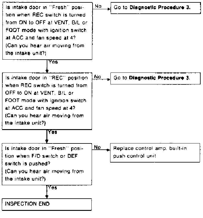
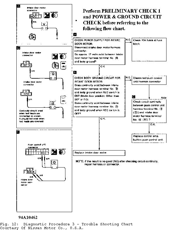
Fig. 4: Preliminary Check 1 - Trouble Shooting Chart Courtesy Of Nissan Motor Co., U.S.A.
PRELIMINARY CHECK 2 - A/C DOES NOT BLOW COLD AIR
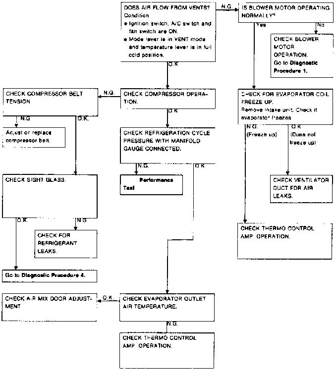
Fig. 5: Preliminary Check 2 - Trouble Shooting Chart Courtesy Of Nissan Motor Co., U.S.A.
PRELIMINARY CHECK 3 - AIR OUTLET DOES NOT CHANGE
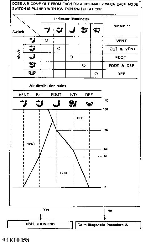
Fig. 6: Preliminary Check 3 - Trouble Shooting Chart Courtesy Of Nissan Motor Co., U.S.A.
PRELIMINARY CHECK 4 - POWER SUPPLY CIRCUIT CHECK FOR A/C
SYSTEM
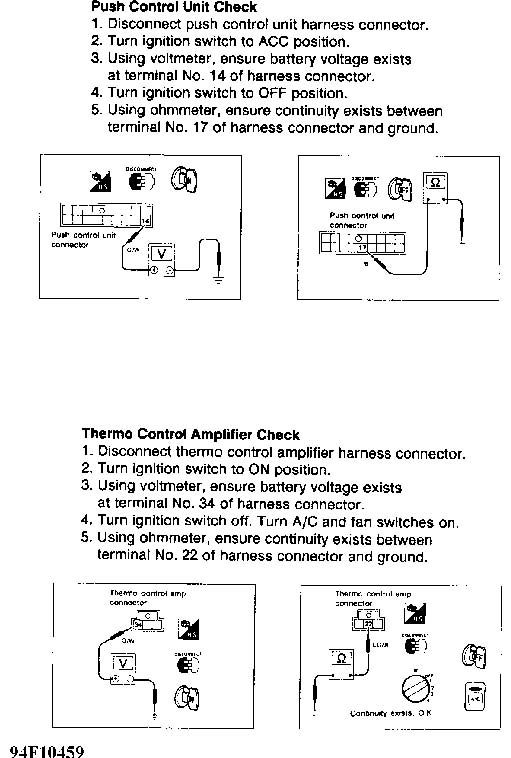
Fig. 7: Preliminary Check 4 - Trouble Shooting Chart Courtesy Of Nissan Motor Co., U.S.A.
DIAGNOSTIC PROCEDURE 1 - BLOWER MOTOR DOES NOT ROTATE
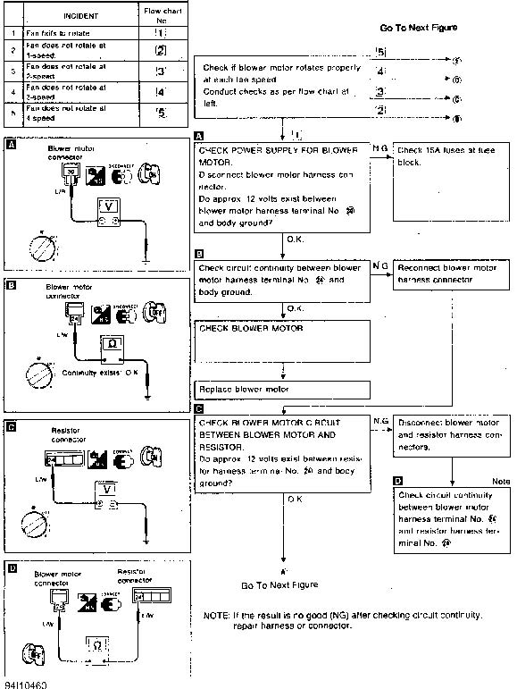
Fig. 8: Diagnostic Procedure 1 - Trouble Shooting Chart (1 Of 2) Courtesy Of Nissan Motor Co., U.S.A.
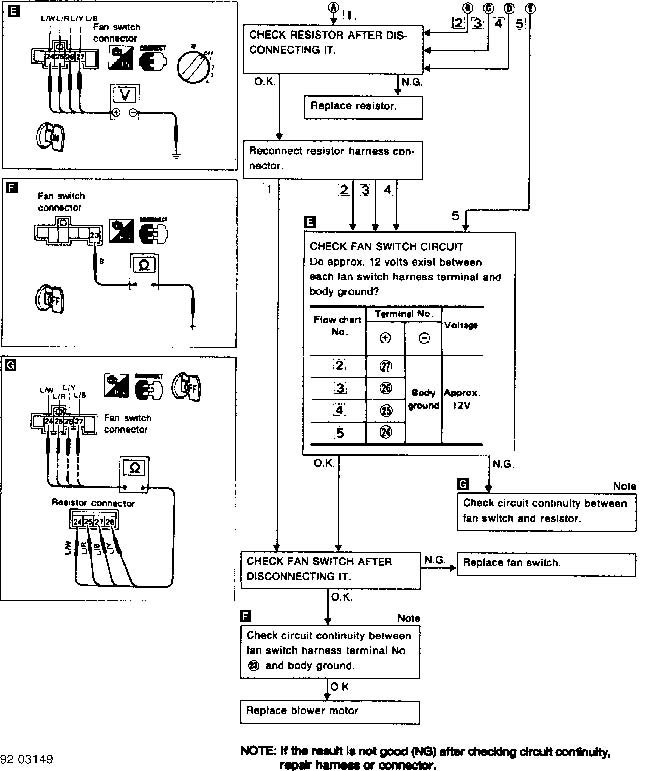
Fig. 9: Diagnostic Procedure 1 - Trouble Shooting Chart (2 Of 2) Courtesy Of Nissan Motor Co., U.S.A.
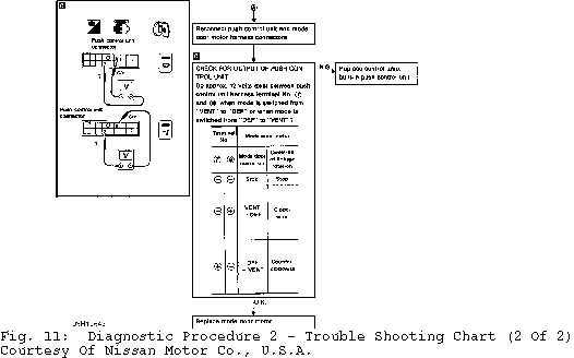
DIAGNOSTIC PROCEDURE 2 - AIR OUTLET DOES NOT CHANGE
DIAGNOSTIC PROCEDURE 3 - INTAKE DOOR DOES NOT CHANGE IN VENT,
BI-LEVEL OR FOOT MODE
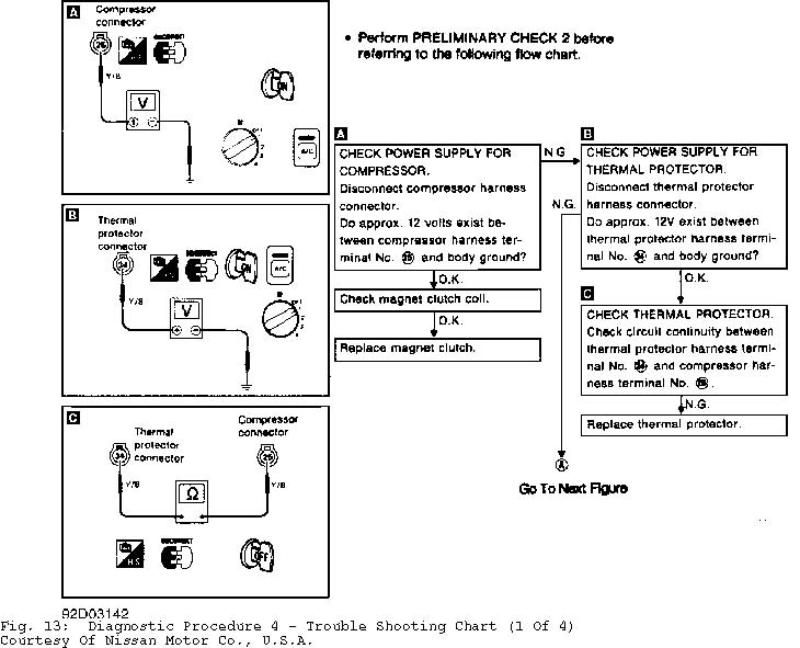
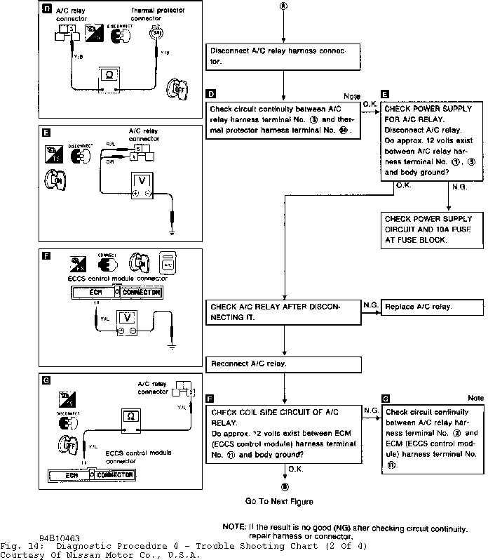
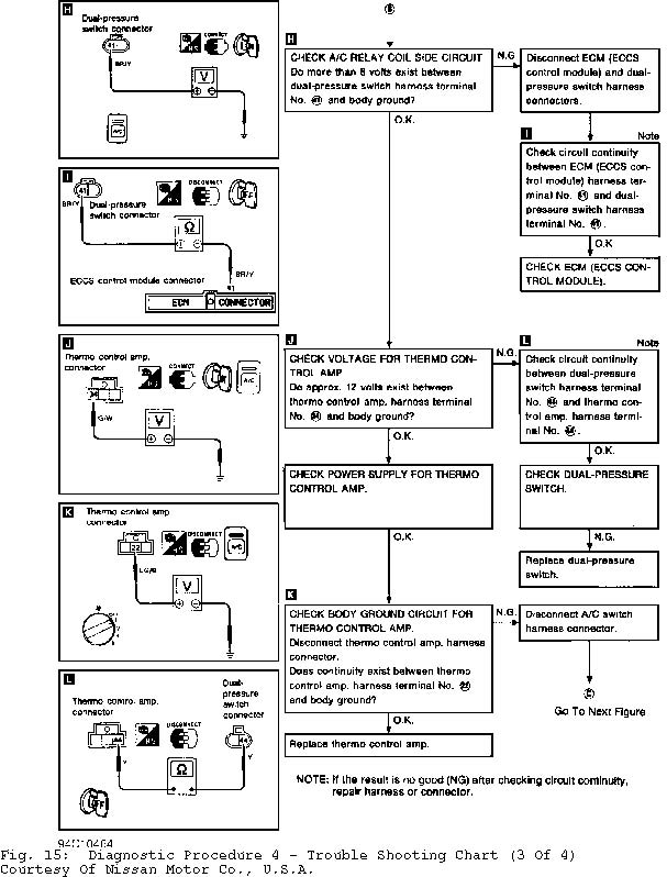
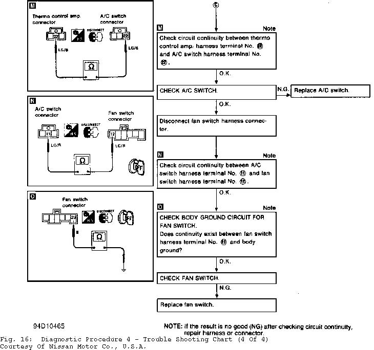
DIAGNOSTIC PROCEDURE 4 - COMPRESSOR (MAGNET) CLUTCH DOES NOT
ENGAGE WITH A/C & FAN SWITCHES ON
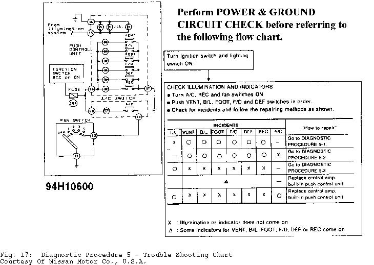
DIAGNOSTIC PROCEDURE 5 - ILLUMINATION OR INDICATORS OF PUSH
CONTROL UNIT DO NOT COME ON
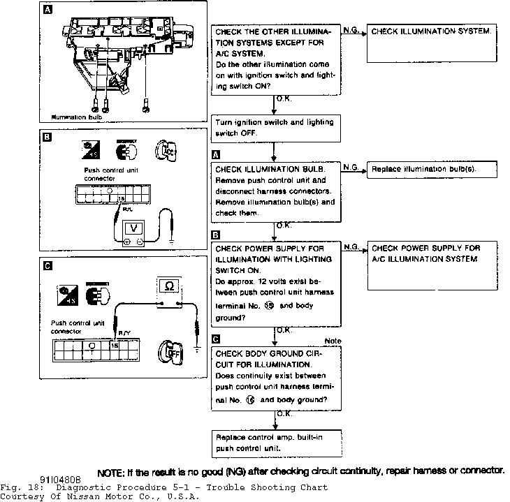
DIAGNOSTIC PROCEDURE 5-1 - ILLUMINATION OR INDICATORS OF PUSH
CONTROL UNIT DO NOT COME ON
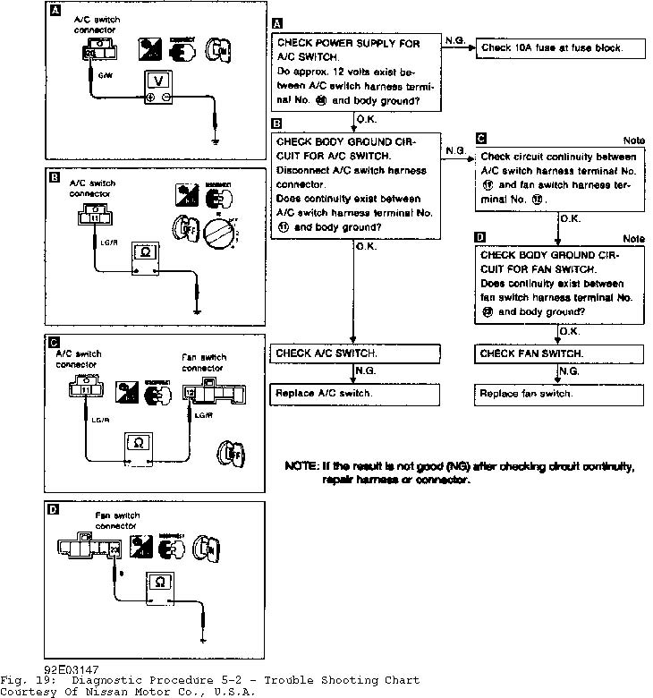
DIAGNOSTIC PROCEDURE 5-2 - ILLUMINATION OR INDICATORS OF PUSH
CONTROL UNIT DO NOT COME ON
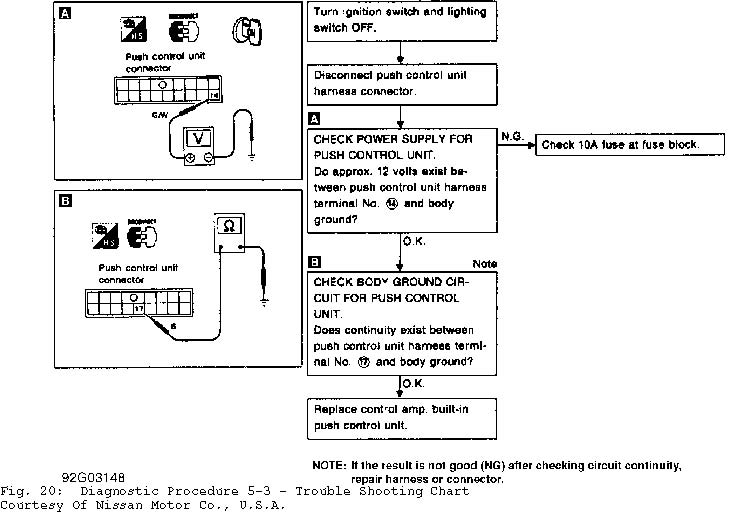
DIAGNOSTIC PROCEDURE 5-3 - ILLUMINATION OR INDICATORS OF PUSH
CONTROL UNIT DO NOT COME ON
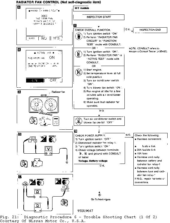
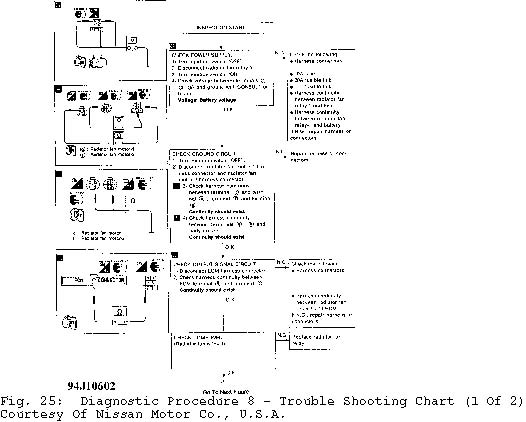
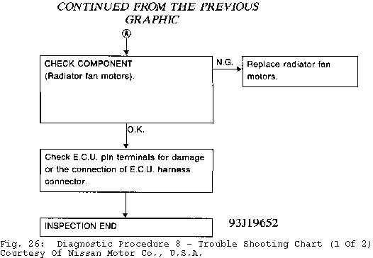
DIAGNOSTIC PROCEDURE 6 - RADIATOR FAN CONTROL (2.0L WITH M/T)

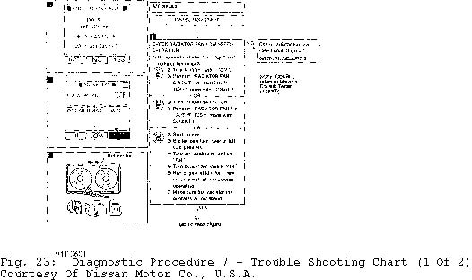
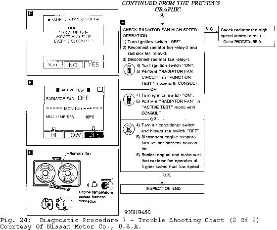
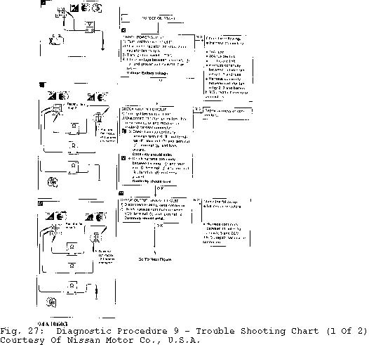
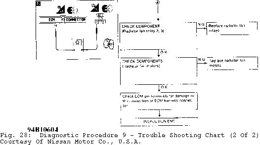
DIAGNOSTIC PROCEDURE 7 - RADIATOR FAN CONTROL (2.0L WITH A/T) DIAGNOSTIC PROCEDURE 8 - RADIATOR FAN CONTROL (2.0L WITH A/T) DIAGNOSTIC PROCEDURE 9 - RADIATOR FAN CONTROL (2.0L WITH A/T)
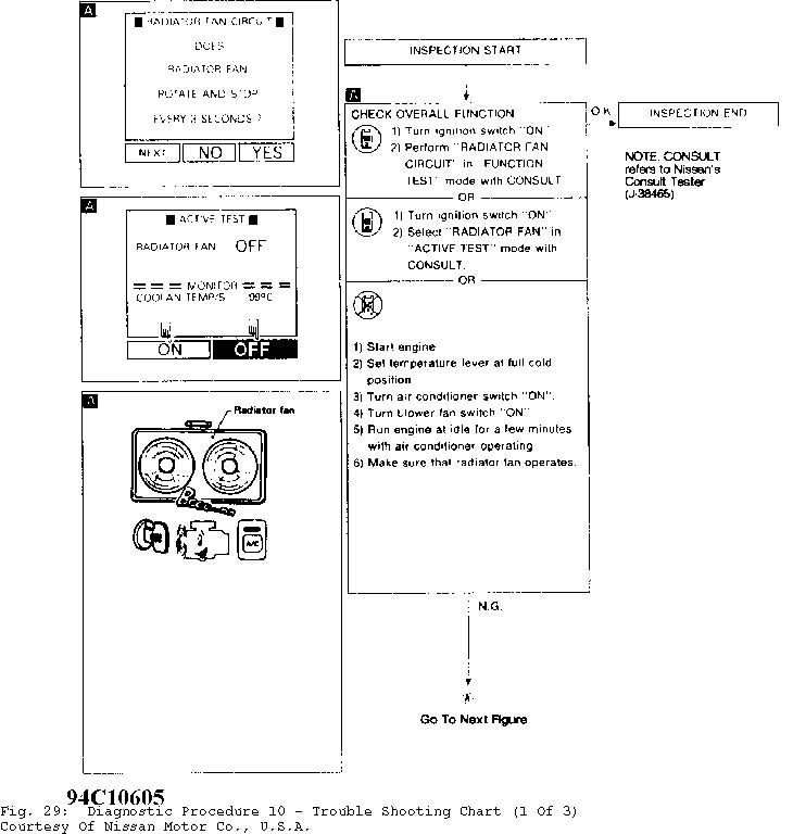
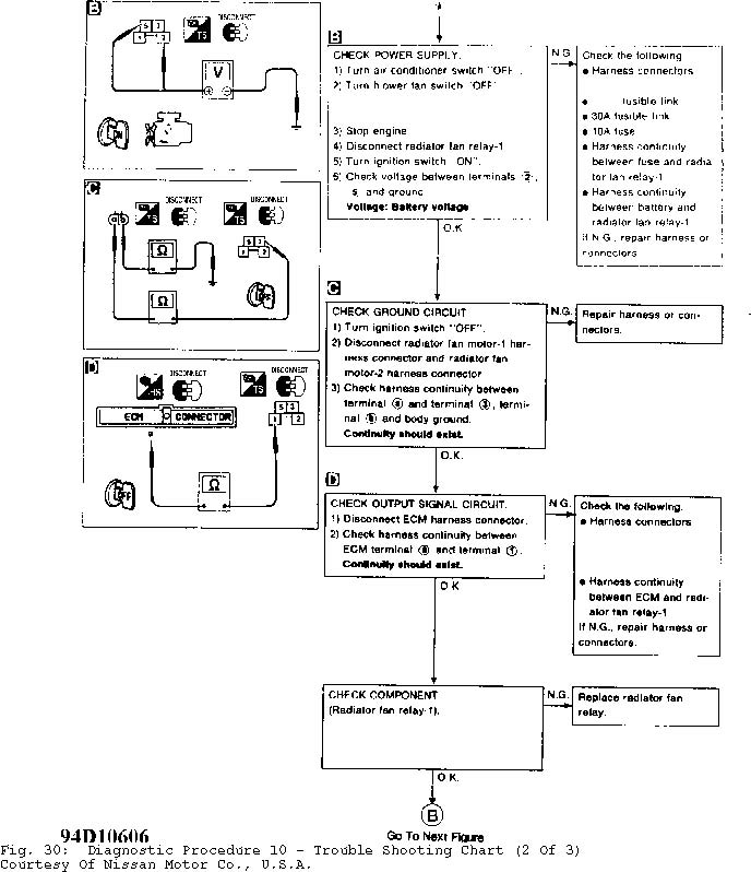
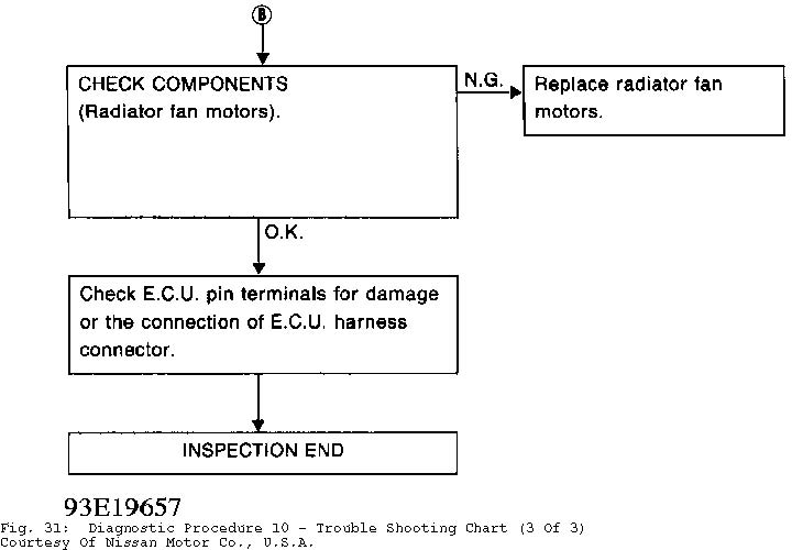
DIAGNOSTIC PROCEDURE 10 - RADIATOR FAN CONTROL (1.6L M/T)
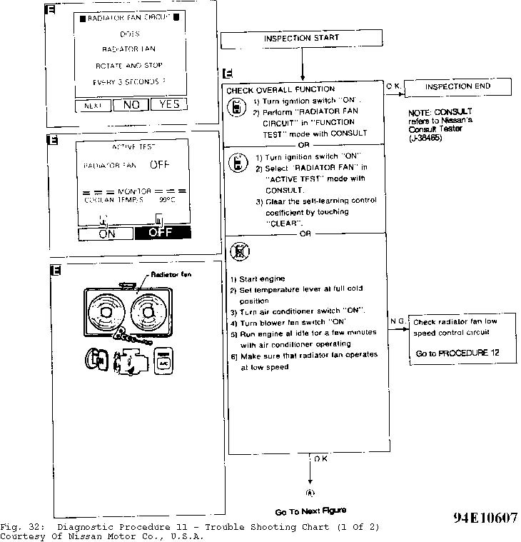
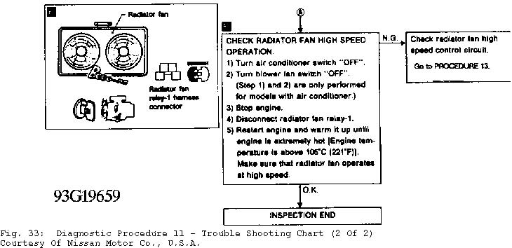
DIAGNOSTIC PROCEDURE 11 - RADIATOR FAN CONTROL (1.6L A/T)
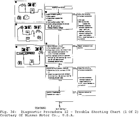
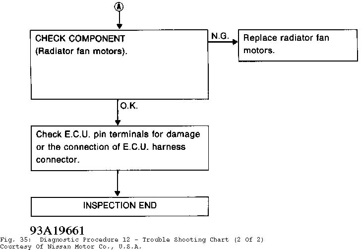
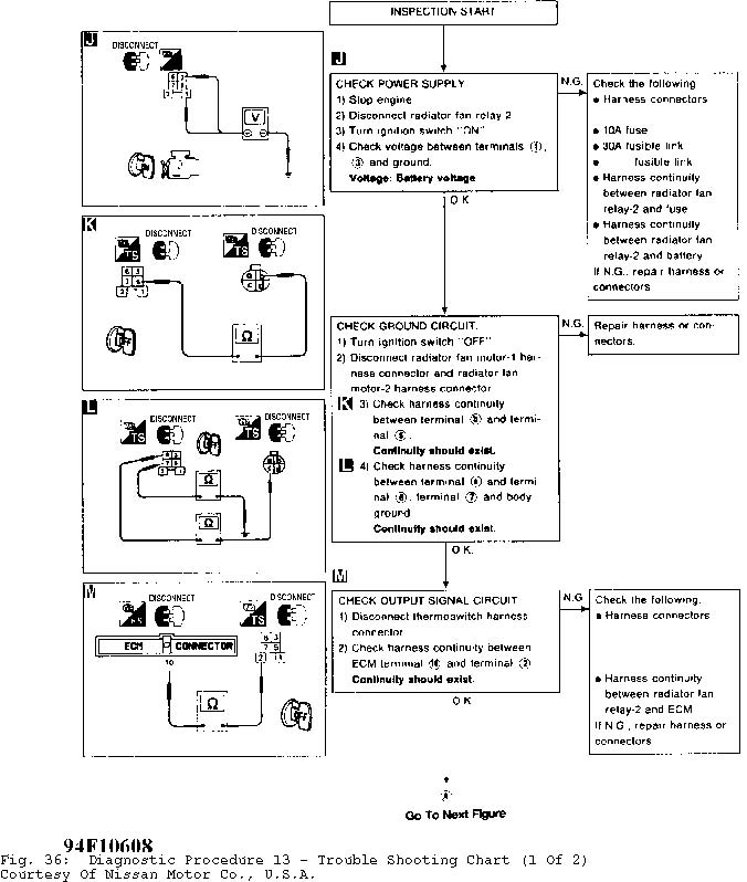
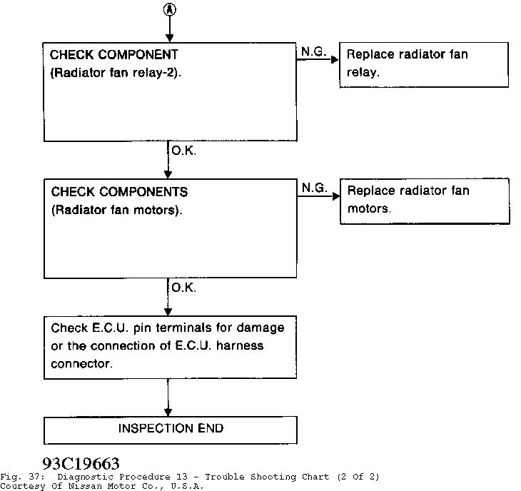
DIAGNOSTIC PROCEDURE 12 - RADIATOR FAN CONTROL (1.6L A/T) DIAGNOSTIC PROCEDURE 13 - RADIATOR FAN CONTROL (1.6L A/T)
TESTING
WARNING: To avoid injury from accidental air bag deployment, read and carefully follow all SERVICE PRECAUTIONS and DISABLING & ACTIVATING AIR BAG SYSTEM procedures in appropriate AIR BAG RESTRAINT SYSTEM article in ACCESSORIES & ELECTRICAL section.
A/C SYSTEM PERFORMANCE
1) Park vehicle out of direct sunlight. Close all doors and open engine hood and windows. Connect A/C manifold gauge set. Determine relative humidity and ambient air temperature.
2) Set temperature control to maximum cold, mode control to face vent and recirculation switch to recirculation positions. Turn blower fan switch to highest position. Start and run engine at 1500 RPM.
3) After running A/C for 10 minutes, check high and low side system pressures. See A/C-HEATER PERFORMANCE TEST table to determine if system is operating within range.
A/C-HEATER PERFORMANCE TEST TABLE
�����������������������������������������������������������������������������������������������������������������������
Ambient Air High Pressure Low Pressure
�� ��
Temp. F ( C) (1) psi (kg/cm ) psi (kg/cm )
| 68 (20) | ......... | 88-132 (6.2-9.3) | ..... | 26-36 (1.8-2.5) | |
|---|---|---|---|---|---|
| 77 (25) | ........ | 118-166 (8.3-11.7) | .... | 27-37 (1.9-2.6) | |
| 86 (30) | ........ | 148-203 (10.4-14.3) | ... | 28-38 (2.0-2.7) | |
| 95 (35) | ........ | 179-237 (12.6-16.7) | ... | 33-46 (2.3-3.2) | |
(1) - Specification is with relative humidity at 50-70%.
�����������������������������������������������������������������������������������������������������������������������
A/C SWITCH
Disconnect negative battery cable. Remove A/C switch from control panel. Turn A/C on. Using an ohmmeter, check continuity between switch terminals. Continuity should exist. If no continuity exists, replace A/C switch.
BLOWER MOTOR
Disconnect wiring harness at blower motor. Apply battery voltage to blower motor terminals. Ensure blower motor operation is smooth. If blower motor operation is rough or not up to speed, replace blower motor.
BLOWER SPEED CONTROL SWITCH
See TESTING in HEATER SYSTEM article.
BLOWER MOTOR RESISTOR
Disconnect harness connector. Check continuity between all resistor terminals. See Fig. 3. Ensure continuity exists. If continuity does not exist, replace resistor.
DUAL-PRESSURE SWITCH
Remove dual-pressure switch connector. Dual-pressure switch is located on top of receiver-drier. Using an ohmmeter, check continuity across switch terminals. See DUAL-PRESSURE SWITCH SPECIFICATIONS table. Replace switch if it does not test as indicated.
DUAL-PRESSURE SWITCH SPECIFICATIONS TABLE
�������������������������������������������������������������������������������������������������������������������������������������������
Pressure: psi (kg/cm � ) System Operation Continuity?
Decreasing To 26-31 (1.8-2.2) ....... Off ..................... No Increasing To 356-412 (25-29) ....... Off ..................... No
Increasing To 26-34 (1.8-2.4) ....... On ..................... Yes Decreasing To 270-327 (19-23) ....... On ..................... Yes
�������������������������������������������������������������������������������������������������������������������������������������������
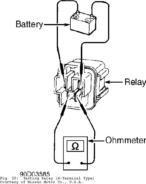
RELAYS
4-Terminal Type
Remove relay to be tested. See Fig. 2. Apply battery voltage between terminals No. 1 and No. 2. See Fig. 38. Check for continuity between remaining relay terminals. Continuity should exist. If no continuity exists, replace relay.
THERMO CONTROL AMPLIFIER
Check the thermo control amplifier as indicated in the THERMO CONTROL AMPLIFIER SPECIFICATIONS table. Replace amplifier if it does not test as specified.
THERMO CONTROL AMPLIFIER SPECIFICATIONS TABLE
�������������������������������������������������������������������������������������������������������������������������������������������
| Evaporator Temp: � F ( � C) Thermo Am | p. Operation | Volts | ||
|---|---|---|---|---|
| Decreasing To 37-38 (2.5-3.5) | ......... | Off | ............. | About 12 |
Increasing To 39-41 (4-5) ............. On .................. Zero
�������������������������������������������������������������������������������������������������������������������������������������������
THERMAL PROTECTOR SWITCH
Check compressor operation at indicated temperature. See THERMAL PROTECTOR SWITCH TEST table. Replace switch if compressor does not test as specified.
THERMAL PROTECTOR SWITCH TEST TABLE
�����������������������������������������������������������������������������������������������������������������������
Compressor Temp. � F ( � C) Compressor Operation
Increasing To 275-293 (135-145) ...................... Off Decreasing To 248-266 (120-130) ....................... On
�����������������������������������������������������������������������������������������������������������������������
REMOVAL & INSTALLATION
WARNING: To avoid injury from accidental air bag deployment, read and
carefully follow all SERVICE PRECAUTIONS and DISABLING &
ACTIVATING AIR BAG SYSTEM procedures in appropriate
AIR BAG RESTRAINT SYSTEM article in ACCESSORIES & ELECTRICAL
section.
A/C COMPRESSOR
Removal
Loosen idler pulley bolt, and remove compressor belt. Discharge A/C system using approved refrigerant recovery/recycling equipment. Disconnect compressor clutch lead. Remove discharge and suction hoses from compressor, and plug hose openings. Remove compressor bolts and compressor.
Installation
To install, reverse removal procedure. Tighten compressor bolts to 33-44 ft. lbs. (45-60 N.m). Coat new "O" rings with refrigerant oil when attaching hoses to compressor. Evacuate and recharge system.
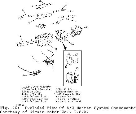
EVAPORATOR & HEATER CORE ASSEMBLY
Removal
Discharge A/C system using approved refrigerant recovery/recycling equipment. Drain cooling system. Disconnect negative battery cable. Deactivate air bag. See appropriate AIR BAG RESTRAINT SYSTEM article in ACCESSORIES & ELECTRICAL section. Remove components in order listed in illustrations. See Figs. 5 and 6.
Installation
To install, reverse removal procedure. Coat NEW "O" rings with refrigerant oil before assembling connections. If installing a new evaporator core, add 2 ounces of refrigerant oil to new core
before installation. Evacuate and recharge system.
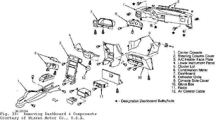
INSTRUMENT PANEL
Disconnect negative battery cable. Deactivate air bag. See AIR BAG SYSTEM SAFETY article in GENERAL SERVICING. Remove components in order listed in illustration. See Fig. 39.
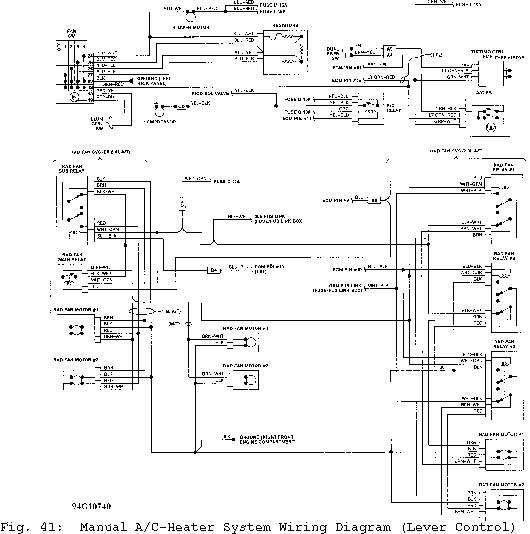
WIRING DIAGRAMS END OF ARTICLE