
�D -ADJUSTMENTS
�1993 Nissan Sentra
1993 ENGINE PERFORMANCE Nissan On-Vehicle Adjustments
Altima, Maxima, NX, Pathfinder, Pickup, Quest, Sentra, 240SX, 300ZX
ENGINE MECHANICAL
Before performing any on-vehicle adjustments to fuel or ignition systems, ensure engine mechanical condition is okay.
VALVE CLEARANCE
NOTE: All engines, except GA16DE and KA24DE, are equipped with hydraulic lifters. No adjustments are required.
Altima, NX (1.6L), Sentra (1.6L) & 240SX
1) Warm engine to normal operating temperature. Remove valve cover and spark plugs. Rotate crankshaft to bring piston No. 1 to TDC on compression stroke (lifters on cylinder No. 1 should be loose).
2) Measure valve clearance on intake valves for cylinders No. 1 and 2 and valve clearance on exhaust valves for cylinders No. 1 and
3. See VALVE CLEARANCE ADJUSTMENT table.
3) Rotate crankshaft 360 degrees to bring piston No. 4 to TDC on compression stroke. Measure valve clearance on intake valves for cylinders No. 3 and 4 and valve clearance on exhaust valves for cylinders No. 2 and 4. See VALVE CLEARANCE ADJUSTMENT table. Adjust valve clearances by replacing lifter shims.
VALVE CLEARANCE ADJUSTMENT TABLE
�����������������������������������������������������������������������������������������������������������������������
Application Hot - In. (mm)
1.6L (GA16DE Engine)
Intake .............................. .008-.019 (.21-.49)
Exhaust ............................. .012-.023 (.30-.58) 2.4L (KA24DE Engine)
Intake .............................. .012-.015 (.30-.38)
Exhaust ............................. .013-.016 (.33-.41)
�����������������������������������������������������������������������������������������������������������������������
IGNITION TIMING
4-CYLINDER IGNITION TIMING
Altima, NX, Pickup, Sentra & 240SX
1) Start engine and warm to normal operating temperature. Turn ignition off. Disconnect throttle position sensor harness connector.
2) Start engine. Increase engine speed to 2000 RPM, 2 or 3 times, then allow engine to return to idle. Engine should be operating smoothly at correct idle RPM. Check ignition timing. See 4-CYLINDER IGNITION TIMING table. See Fig. 1.
3) If ignition timing is incorrect, loosen hold-down bolt and turn distributor to adjust ignition timing. Turn ignition off and connect throttle position sensor harness connector. Recheck ignition timing.
4-CYLINDER IGNITION TIMING TABLE (Degrees BTDC @ RPM)
���������������������������������������������������������������������������������������������������������������������������
| Application | Man. Trans. | (1) Auto. Trans. | ||||
|---|---|---|---|---|---|---|
| Altima & 240SX | ..... | 18-22 @ 700-800 | ..... | 18-22 @ 700-800 | ||
| NX & Sentra | ||||||
| 1.6L | .............. | 8-12 @ 600-700 | ....... | 8-12 @ 800-900 | ||
| 2.0L | .............. | 13-17 @ 800-900 | ..... | 13-17 @ 800-900 | ||
| Pickup | ............. | 8-12 @ 750-850 | ....... | 8-12 @ 750-850 | ||
(1) - Automatic transmission/transaxle in Neutral.
���������������������������������������������������������������������������������������������������������������������������
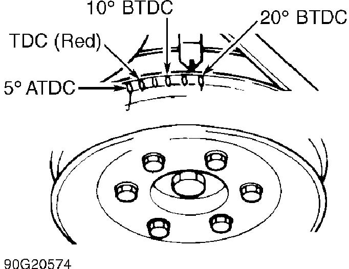
Fig. 1: Ignition Timing Marks (Altima, Pickup 4-Cylinder, & 240SX Shown; NX & Sentra Similar) Courtesy of Nissan Motor Co., U.S.A.
V6 IGNITION TIMING
Maxima (VG30E), Pathfinder & Pickup V6
1) Start engine and warm to normal operating temperature. Increase engine speed to 2000 RPM, 2 or 3 times, then allow engine to return to idle.
2) With engine correct idle RPM, check ignition timing. See V6 IGNITION TIMING table. See Fig. 2. If ignition timing is incorrect, loosen hold-down bolt and turn distributor to adjust ignition timing.
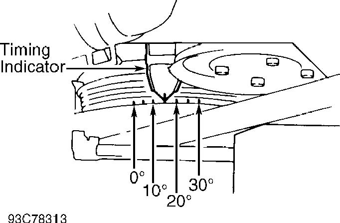
Fig. 2: Locating Ignition Timing Marks (V6 Except 300ZX) Courtesy of Nissan Motor Co., U.S.A.
Maxima (VE30DE) & 300ZX
1) Ensure engine is at normal operating temperature. Turn ignition off. Disconnect IACV-AAC valve harness connector. Disconnect Throttle Position (TP) sensor.
2) Start engine. Increase engine speed to 2000 RPM, 2 or 3 times, then allow engine to return to idle. Check ignition timing. See V6 IGNITION TIMING table. See Fig. 2 or 3. If ignition timing is incorrect, loosen hold-down bolt and turn crankshaft position sensor.
Quest
1) Ensure engine is at normal operating temperature. Turn ignition off. Disconnect IACV-AAC valve harness connector. Start engine. Increase engine speed to 2000 RPM, 2 or 3 times, then allow engine to return to idle.
2) Check ignition timing. See V6 IGNITION TIMING table. See Fig. 2. If ignition timing is incorrect, loosen hold-down bolt and turn distributor to adjust ignition timing.
V6 IGNITION TIMING TABLE (Degrees BTDC @ RPM)
�����������������������������������������������������������������������������������������������������������������������������
Application Man. Trans. (1) Auto. Trans.
Maxima, Pathfinder,
| Pickup & Quest | ...... | 13-17 @ 700-800 | .... | 13-17 @ 700-800 | ||
|---|---|---|---|---|---|---|
| 300ZX | ||||||
| Non-Turbo | ........... | 13-17 @ 650-750 | .... | 13-17 @ 720-820 | ||
| Turbo | ............... | 13-17 @ 650-750 | .... | 13-17 @ 700-800 | ||
(1) - Automatic transmission/transaxle in Neutral.
�����������������������������������������������������������������������������������������������������������������������������
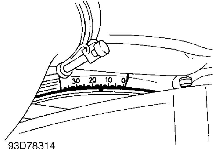
Fig. 3: Locating Ignition Timing Marks (300ZX) Courtesy of Nissan Motor Co., U.S.A.
IDLE SPEED & MIXTURE
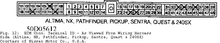
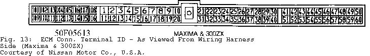
NOTE: Mixture adjustment is NOT a normal tune-up procedure. DO NOT adjust unless mixture control unit is replaced or vehicle fails emissions tests. For ECM connector terminal identification, see Figs. 12 and 13.
4-CYLINDER IDLE SPEED
Altima, NX, Pickup, Sentra & 240SX
1) Start engine and warm to normal operating temperature. Turn ignition off. Disconnect Throttle Position (TP) sensor harness connector. Start engine.
2) Increase engine speed to 2000 RPM, 2 or 3 times, then allow engine to return to idle. Ensure ignition timing is set
correctly. Check idle speed. See 4-CYLINDER IDLE SPEED & CO% LEVEL table.
3) If idle speed is incorrect, adjust idle speed by turning idle speed adjusting screw. See Fig. 4, 5 or 6. With idle speed correctly set, turn ignition off. Reconnect TP sensor and recheck idle speed.
4-CYLINDER IDLE SPEED & CO% LEVEL TABLE
�����������������������������������������������������������������������������������������������������������������������������
| (1) Idle | (2) Idle | (3) CO | |||||||||||
|---|---|---|---|---|---|---|---|---|---|---|---|---|---|
| Application | RPM | RPM | Level (%) | ||||||||||
| Altima | .......... | (4) 650-750 | ... | (4) 600-700 | ..... | (5) 7 | |||||||
| NX & Sentra | |||||||||||||
| 1.6L | |||||||||||||
| Auto. Trans. | ... | (4) 750-850 | ... | (4) 675-775 | ..... | (5) 7 | |||||||
| Man. Trans. | ...... | 600-700 | ..... | 550-650 | ......... | (5) 7 | |||||||
| 2.0L | |||||||||||||
| Auto. Trans. | ... | (4) 750-850 | ... | (4) 700-800 | .... | (5) 10 | |||||||
| Man. Trans. | ...... | 750-850 | ..... | 700-800 | ........ | (5) 10 | |||||||
| Pickup | .......... | (4) 650-750 | ... | (4) 600-700 | ..... | (5) 5 | |||||||
| 240SX | ........... | (4) 650-750 | ... | (4) 600-700 | ..... | (5) 7 | |||||||
- (1)
- - With throttle position sensor connected.
- (2)
- - With throttle position sensor disconnected.
- (3)
- - Measured in self-diagnostic mode.
- (4)
- - Automatic transmission/transaxle in Neutral.
- (5)
- - Maximum CO% level.
�����������������������������������������������������������������������������������������������������������������������������
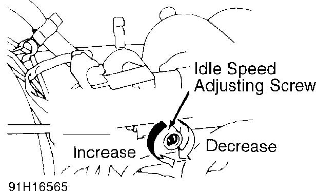
Fig. 4: Adjusting Idle Speed (NX & Sentra) Courtesy of Nissan Motor Co., U.S.A.
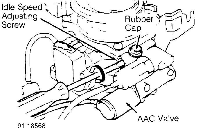
Fig. 5: Adjusting Idle Speed (Pickup 4-Cylinder; Altima Is Similar) Courtesy of Nissan Motor Co., U.S.A.
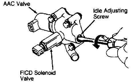
Fig. 6: Adjusting Idle Speed (240SX) Courtesy of Nissan Motor Co., U.S.A
4-CYLINDER IDLE MIXTURE
Altima, NX, Sentra & 240SX
1) Start engine and warm to normal operating temperature. Increase engine speed to 2000 RPM for 2 minutes. Enter Mode II of vehicle’s self-diagnostic system. See appropriate G - TESTS W CODES in the ENGINE PERFORMANCE section.
2) Locate ECM. See ECM LOCATIONS table. Start engine. Raise engine speed to 2000 RPM. With idle speed and ignition timing set correctly, ensure Malfunction Indicator Light (MIL) and Red light on ECM goes on and off more than 5 times during a 10 second period.
3) If both lights operate as indicated, idle mixture is correctly set. If both lights do not operate as indicated, turn ignition off. Disconnect negative battery cable. Disconnect ECM and oxygen sensor wiring harness connector.
4) Using a jumper wire, connect oxygen sensor wiring harness connector terminal to ground. Check continuity between terminal No. 19 of ECM wiring harness connector and ground.
5) If continuity exists, remove jumper wire, reconnect ECM and go to next step. If continuity does not exist, repair wiring harness. After repairs, reconnect negative battery cable. Recheck idle speed and ignition timing.
6) Disconnect engine coolant temperature sensor. Connect a 2500-ohm resistor between sensor wiring harness connector terminals. If vehicle is equipped with Pulse Air Injection System (PAIR), disconnect PAIR solenoid valve wiring harness connector. Connect negative battery cable.
7) Start engine and warm to normal operating temperature. Increase engine speed to 2000 RPM, 2 or 3 times. Check idle mixture (CO% level). See 4-CYLINDER IDLE SPEED & CO% LEVEL table under 4CYLINDER IDLE SPEED. Remove 2500-ohm resistor from engine coolant temperature sensor wiring harness connector. Reconnect sensor.
8) If idle mixture (CO% level) is incorrect, go to next step. If idle mixture (CO% level) is correct, replace oxygen sensor. Start engine and increase engine speed to 2000 RPM. Ensure MIL on dash goes on and off more than 5 times during a 10 second period with engine running at 2000 RPM. If MIL does not perform as indicated, go to next step.
9) Reconnect oxygen sensor. Perform self-diagnostics. See appropriate G - TESTS W/ CODES article in the ENGINE PERFORMANCE section. If no fault codes are present, check fuel pressure, airflow meter, injectors and engine coolant temperature sensor for faults. If all systems are operating correctly but idle mixture is still incorrect, replace ECM.
ECM LOCATIONS TABLE
�����������������������������������������������������������������������������������������������������������������������������
Application Location
Altima ................................. Under Center Console Maxima, NX & Sentra ....... Under Dash, Behind Center Console Pathfinder & Pickup .................... Under Passenger Seat Quest ...................................... Behind Glove Box 240SX .............................. Under Right Side Of Dash 300ZX ....................... Below Glove Box, Behind Console
�����������������������������������������������������������������������������������������������������������������������������
Pickup
1) Start engine and warm to normal operating temperature. Run engine at 2000 RPM for 2 minutes. Perform self-diagnostics. See appropriate G - TESTS W/ CODES article in the ENGINE PERFORMANCE section.
2) Locate ECM. See ECM LOCATIONS table. With idle speed and ignition timing correctly set, increase engine speed to 2000 RPM for 2 minutes. If Green LED on ECM does not go on and off more than 5 times
during a 10 second period, go to step 4).
3) If Green LED goes on and off more than 5 times during a 10 second period, enter and set self-diagnostic system to Mode II. Red and Green LEDs on ECM should blink simultaneously. If both LEDs blink, idle mixture is correct. If both LEDs do not blink simultaneously, go to step 6).
4) Turn off engine. Disconnect negative battery cable. Disconnect oxygen sensor and ECM wiring harness connector. Using a jumper wire, ground oxygen sensor wiring harness connector. Check continuity between terminal No. 19 of ECM wiring harness connector and ground.
5) If continuity exists, remove jumper wire. Reconnect ECM and go to next step. If no continuity exists, repair wiring harness. After repairs, reconnect negative battery cable. Recheck idle speed and ignition timing.
6) Disconnect engine coolant temperature sensor. Connect a 2500-ohm resistor between engine coolant temperature sensor wiring harness. Disconnect Pulse Air Injection System (PAIR) valve hose. Reconnect negative battery cable.
7) Start engine and warm to normal operating temperature. Increase engine speed to 2000 RPM, 2 or 3 times and return to idle. Check CO% level at idle speed. See 4-CYLINDER IDLE SPEED & CO% LEVEL table under 4-CYLINDER IDLE SPEED. Remove 2500-ohm resistor from engine coolant temperature sensor wiring harness and reconnect sensor.
8) If CO% level is incorrect, go to next step. If CO% level is correct, replace oxygen sensor. Start engine and increase engine speed to 2000 RPM. Ensure Green LED on ECM goes on and off more than 5 times during a 10 second period with engine running at 2000 RPM. If Green LED does not perform as indicated, go to next step.
9) Ensure all components and wiring harness connectors are connected. Perform self-diagnostics. See G - TESTS W/ CODES article in the ENGINE PERFORMANCE section. If no fault codes are present, check fuel pressure, airflow meter, injectors and engine coolant temperature sensor for faults. If all systems are operating correctly but idle CO% level is still incorrect, replace ECM.
V6 IDLE SPEED
Maxima (VG30E)
1) Start engine and warm to normal operating temperature. Run engine at 2000 RPM for 2 minutes. Perform self-diagnostics. See appropriate G - TESTS W/ CODES article in the ENGINE PERFORMANCE section.
2) With ignition timing correctly set, check idle speed (automatic transaxle in Neutral). See V6 IDLE SPEED & CO% LEVEL table. If idle speed is incorrect, close Auxiliary Air Control (AAC) valve by turning diagnostic mode selector screw on ECM fully clockwise.
3) Adjust idle speed by turning idle speed adjusting screw. See Fig. 7. Open AAC valve by turning diagnostic mode selector screw on ECM fully counterclockwise. Idle speed should remain within specified range.
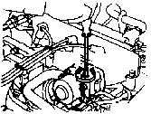
Fig. 7: Locating Idle Speed Adjusting Screw (Maxima VG30E) Courtesy of Nissan Motor Co., U.S.A.
V6 IDLE SPEED & CO% LEVEL TABLE
���������������������������������������������������������������������������������������������������������������������������������
(1) Idle (2) Idle (3) CO Application RPM RPM Level (%)
Maxima VG30E ......... (4) 650-750 ..... (4) 700 ........ 0.2-8.0 VE30DE ........ (4) 650-750 ... (4) 650-750 ...... 0.2-8.0
Pathfinder & Pickup Auto. Trans. .. (4) 700-800 ..... (4) 700 ........ 0.2-8.0 Man. Trans. ..... 700-800 ....... 700 ............ 0.2-8.0
Quest .......... (4) 650-750 ... (4) 700-800 ...... 0.2-8.0
300ZX Auto. Trans. Non-Turbo ..... (4) 720-820 ..... (4) 720 ........ 0.2-8.0 Turbo ......... (4) 700-800 ..... (4) 700 ........ 0.2-8.0 Man. Trans. ..... 650-750 ....... 650 ............ 0.2-8.0
- (1)
- - With Auxiliary Air Control (AAC) valve connected.
- (2)
- - With Auxiliary Air Control (AAC) valve disconnected.
- (3)
- - Measured in Self-Diagnostic Mode II.
- (4)
- - Automatic transmission/transaxle in Neutral.
���������������������������������������������������������������������������������������������������������������������������������
Maxima (VE30DE), Pathfinder, Pickup, Quest & 300ZX Turbo 1) Start engine and warm to normal operating temperature. Increase engine speed to 2000 RPM, 2 or 3 times and return to idle.
2) With ignition timing correctly set, check idle speed (automatic transmission in Neutral). See V6 IDLE SPEED & CO% LEVEL table. If idle speed is incorrect, turn ignition off. Disconnect IACVAAC valve wiring harness connector.
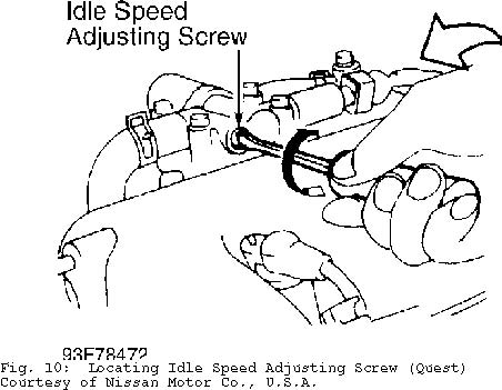
3) Adjust idle speed by turning idle speed adjusting screw. See Figs. 8-11. Reconnect (AAC) valve harness connector. Start engine and increase engine speed to 2000 RPM, 2 or 3 times and return to idle. Recheck idle speed to ensure correct setting.
NOTE: On 300ZX, accel-drum unit synchronizes opening time of left and right throttle plates. If accel-drum unit is removed, it must be adjusted after installation to ensure throttle plates open at the same time. Refer to 3.0L V6 - VG30 article in the ENGINES section.
300ZX (Non-Turbo)
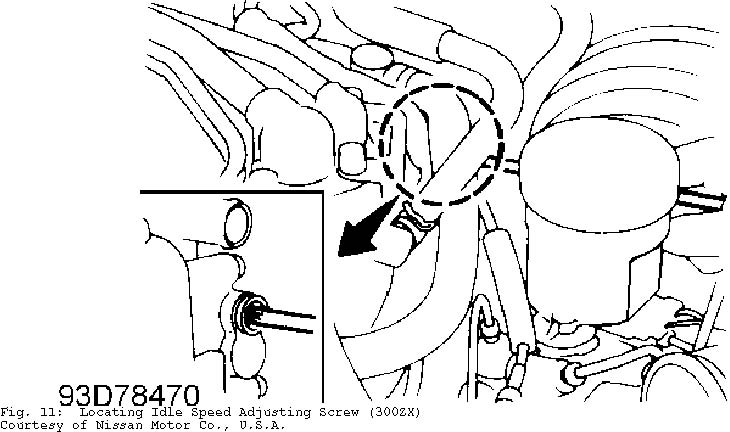
Start engine and warm to normal operating temperature. Ensure ignition timing is correct. Check idle speed. See V6 IDLE SPEED & CO% LEVEL table. If idle speed is incorrect, turn ignition off. Disconnect TP sensor connector. Start engine. Adjust idle speed by turning idle speed adjusting screw. See Fig. 11.
Fig. 8: Locating Idle Speed Adjusting Screw (Maxima VE30DE) Courtesy of Nissan Motor Co., U.S.A.
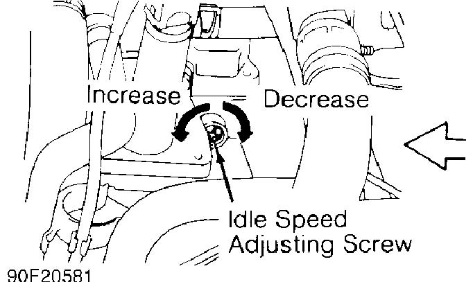
Fig. 9: Locating Idle Speed Adjusting Screw (Pathfinder & Pickup V6) Courtesy of Nissan Motor Co., U.S.A.
V6 IDLE MIXTURE
NOTE: No idle mixture adjustment procedure is available. If the
following tests determine idle mixture is incorrect, a
faulty component is responsible and must be replaced.
Maxima, Pathfinder, Pickup & Quest
1) Start engine and warm to normal operating temperature. With idle speed and timing correctly set, enter Mode II of vehicle’s self-diagnostic system. See G - TESTS W/ CODES article in the ENGINE PERFORMANCE section.
2) Start engine. Increase engine speed to 2000 RPM for 2 minutes. Ensure MIL goes on and off more than 5 times during a 10 second period. If MIL operates as indicated, idle mixture is correct. If MIL does not operate as indicated, go to next step.
3) Turn ignition off. Disconnect negative battery cable. Disconnect oxygen sensor and ECM wiring harness connector. Using a jumper wire, ground center terminal of oxygen sensor wiring harness connector.
4) Check continuity between terminal No. 19 (terminal No. 29 on Maxima) of ECM wiring harness connector and ground. If no continuity exists, repair or replace wiring harness. Reconnect negative battery cable. Repeat idle speed and ignition timing adjustment procedures and check idle mixture.
5) If continuity exists, remove oxygen sensor jumper wire and reconnect ECM. Disconnect engine coolant temperature sensor connector. Connect a 2500-ohm resistor to engine coolant temperature sensor wiring harness.
6) Reconnect negative battery cable. Start engine. Increase
engine speed to 2000 RPM, 2 or 3 times, then allow engine to return to idle. Check idle mixture (CO% level). See V6 IDLE SPEED & CO% LEVEL table under V6 IDLE SPEED.
7) If idle mixture (CO% level) is incorrect, go to next step. If idle mixture (CO% level) is correct, replace oxygen sensor. Ensure Green LED on ECM goes on and off more than 5 times during a 10 second period with engine running at 2000 RPM. If LED does not turn on and off as specified, go to next step.
8) Reconnect oxygen sensor. Perform self-diagnostics. See appropriate G - TESTS W/ CODES article in the ENGINE PERFORMANCE section. If no fault codes are present, check fuel pressure, airflow meter, injectors and engine coolant temperature sensor for faults. If all systems are operating correctly but idle CO% level is still incorrect, replace ECM.
300ZX
1) Start engine and warm to normal operating temperature. Perform self-diagnostics. See G - TESTS W/ CODES article in the ENGINE PERFORMANCE section.
2) Ensure idle speed and ignition timing are correct. Locate ECM. See ECM LOCATIONS table under 4-CYLINDER IDLE MIXTURE. Increase engine speed to 2000 RPM for another 2 minutes.
3) Enter and set self-diagnostic system to Mode II. See appropriate G - TESTS W/ CODES article in the ENGINE PERFORMANCE section. Ensure Red LED on ECM goes on and off more than 5 times during a 10 second period with engine running at 2000 RPM. If LED does not turn on and off as specified, replace left oxygen sensor and repeat idle mixture procedure. If Red LED does not come on at all, go to step 7). If Red LED operates as stated, go to next step.
NOTE: If idle mixture is still incorrect (Red LED on ECM does not
go on and off more than 5 times during a 10 second period)
after replacing left oxygen sensor, perform self-diagnostic
procedure. Also check fuel pressure, airflow meter,
injectors and engine coolant temperature sensor.
4) Increase engine speed to 2000 RPM, 2 or 3 times. Red LED on ECM should go on and off more than 5 times during a 10 second period with engine running at 2000 RPM. If LED does not turn on and off as specified, replace right oxygen sensor and repeat test procedure starting at step 3). If Red LED does not come on at all, go to next step. If Red LED operates as stated, oxygen sensors and idle mixture are correct.
5) Turn ignition off. Disconnect negative battery cable. To check right oxygen sensor, disconnect wiring harness connector. Disconnect ECM 76-pin connector.
6) Check continuity between terminal No. 29 of ECM 76-pin connector and center terminal of oxygen sensor wiring harness connector. If continuity exists, go to step 9). If continuity does not exist, repair wiring harness and repeat idle mixture procedure starting at step 3).
7) Turn ignition off. Disconnect negative battery cable. To check left oxygen sensor, disconnect wiring harness connector. Disconnect ECM 76-pin connector. Check continuity between terminal No. 55 of ECM 76-pin connector and center terminal of oxygen sensor wiring harness connector.
8) If continuity exists, go to next step. If continuity does not exist, repair wiring harness and repeat idle mixture procedure starting at step 3).
9) Reconnect ECM 76-pin connector. Disconnect engine coolant temperature sensor connector. Connect a 2500-ohm resistor to engine coolant temperature sensor wiring harness.
10) Reconnect negative battery cable. Start engine and warm
to normal operating temperature (coolant gauge needle in middle). Increase engine speed to 2000 RPM, 2 or 3 times, then allow engine to return to idle.
11) Check idle mixture (CO% level). See V6 IDLE SPEED & CO% LEVEL table under V6 IDLE SPEED. If idle mixture (CO% level) is correct, replace right oxygen sensor and repeat procedure starting at step 3).
12) If idle mixture (CO% level) is incorrect, reconnect oxygen sensor. Perform self-diagnostics. See G - TESTS W/ CODES article in the ENGINE PERFORMANCE section. Service all fault codes. If no fault codes are present, check fuel pressure, airflow meter, injectors and engine coolant temperature sensor for faults. If all systems are operating correctly but idle CO% level is still incorrect, replace ECM.
THROTTLE POSITION SENSOR & THROTTLE SWITCH ADJUSTMENT
THROTTLE POSITION (TP) SENSOR (4-CYLINDER ENGINES)
NOTE: Faults in TP sensor circuit may set Code 43. To test system, see CODE 43 diagnostic procedure in G - TESTS W/ CODES article in the ENGINE PERFORMANCE section.
Altima, NX, Pickup, Sentra & 240SX
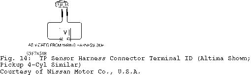
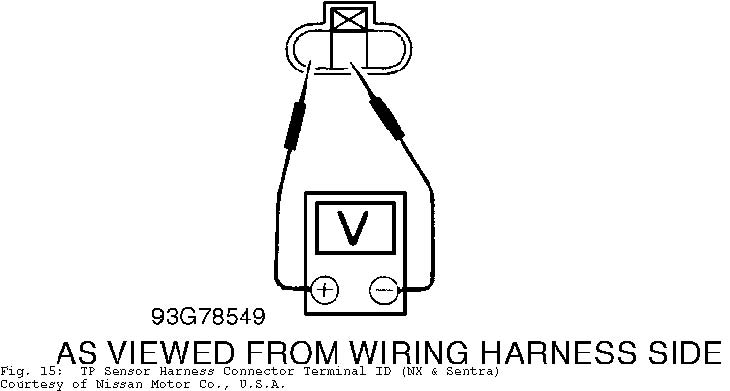
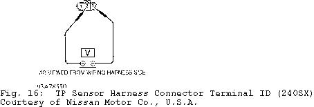
Turn ignition off. Ensure TP sensor wiring harness connector is securely connected. Adjust TP sensor by loosening mounting bolts and rotating sensor body until output voltage is within specification. See 4-CYLINDER TP SENSOR VOLTAGE table. See Fig. 14, 15 or 16.
4-CYLINDER TP SENSOR VOLTAGE TABLE (1)
�����������������������������������������������������������������������������������������������������������������������
Application Voltage
Altima M/T & 240SX M/T (2) ....................... .30-.70 NX & Sentra M/T (2) .............................. .45-.55 Pickup ........................................... .40-.60
- (1)
- - Voltage is measured at wiring harness side with TP sensor connected and ignition switch in the ON position.
- (2)
- - No adjustment procedure is given for A/T models.
�����������������������������������������������������������������������������������������������������������������������
THROTTLE POSITION (TP) SENSOR (V6 ENGINES)
NOTE: TP sensor is not adjustable, however, faults in TPS circuit may set Code 43. To test system, see CODE 43 diagnostic procedure in appropriate G - TESTS W/ CODES article in the ENGINE PERFORMANCE section.
THROTTLE POSITION SWITCH (V6 ENGINES)
Disconnect idle switch. Connect ohmmeter between center and outer terminals. Check idle switch off/on speed, while closing throttle valve. Idle switch should turn on at 100-400 RPM (800-1100 RPM on Maxima & 300ZX). If idle switch does not perform as indicated, loosen idle switch hold-down screws and rotate switch body to set off/on speed to specification.