
AIR BAG RESTRAINT SYSTEM
�1993 Nissan Sentra
ACCESSORIES & SAFETY EQUIPMENT Nissan Motor Co. Air Bags
Nissan; Altima, Maxima, NX, Sentra & 300ZX
WARNING: To avoid injury from accidental air bag deployment, read and carefully follow all WARNINGS and SERVICE PRECAUTIONS.
DESCRIPTION & OPERATION
Driver’s air bag is located in center of steering wheel pad. Supplemental Restraint System (SRS) will deploy in a moderate-tosevere frontal collision. Air bag(s) and seat belt pretensioners should not deploy in a side-impact, rear-impact or a roll-over accident. SRS will only operate when ignition switch is in ON or START position.
SRS consists of one center impact sensor (3 impact sensors on 300ZX), air bag module, spiral cable, tunnel sensor, safing (safety) sensor and an electronic diagnostic (control) unit, located under center console, that sends electrical signals to activate SRS.
When SRS receives a signal from front impact sensor(s), tunnel and safing sensors, air bag module(s) deploy and then quickly deflate.
AIR BAG WARNING LIGHT
The AIR BAG warning light, located in the instrument cluster, monitors the air bag system circuit. AIR BAG warning light monitors one center impact sensor (3 impact sensors on 300ZX), tunnel sensor, safing (safety) sensor and related wiring harnesses.
When ignition switch is in ON or START position, AIR BAG warning light will glow for about 7 seconds and then turn off, indicating system is operational. If AIR BAG warning light does not come on, remains on or flashes intermittently, air bag system will not operate properly and must be serviced.
IMPACT SENSORS
Altima, Maxima, NX & Sentra
One center impact sensor is located in center of vehicle front. Tunnel sensor and safing (safety) sensor are located along transmission tunnel, near middle of vehicle. See Figs. 1 and 2.
300ZX
Front impact sensors are located on right side, center and left side of vehicle front. Tunnel sensor and safing (safety) sensor are located along transmission tunnel, near middle of vehicle. See Fig. 3.
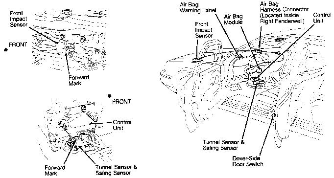
Fig. 1: Locating Supplemental Restraint System Components (Maxima) Courtesy of Nissan Motor Co., U.S.A.
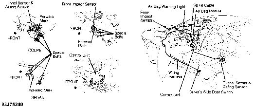
Fig. 2: Locating Supplemental Restraint System Components (NX & Sentra Shown; Altima Is Similar) Courtesy of Nissan Motor Co., U.S.A.
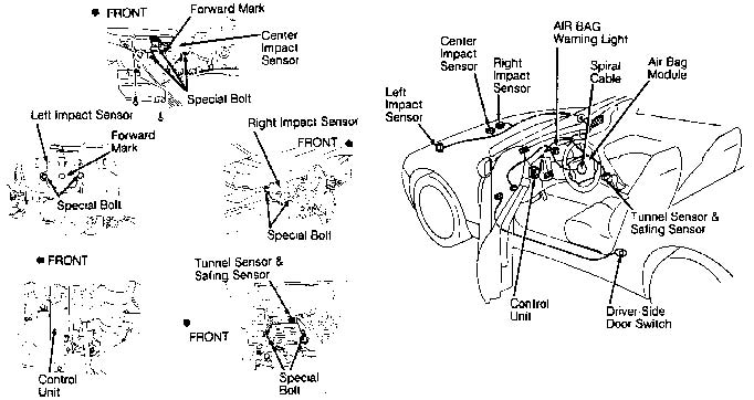
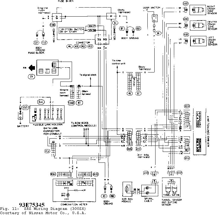
Fig. 3: Locating Supplemental Restraint System Components (300ZX) Courtesy of Nissan Motor Co., U.S.A.
SYSTEM OPERATION CHECK
Supplemental Restraint System (SRS)
When ignition switch is turned to ON or START position, AIR BAG warning light should come on for about 7 seconds and then turn off, indicating system is operational. If AIR BAG warning light does not operate as described, a problem exists in SRS. See DIAGNOSTIC PROCEDURES under DIAGNOSIS & TESTING.
SERVICE PRECAUTIONS
Observe these precautions when working with air bag systems:
- *
- Disable SRS before servicing any SRS or steering column component. See DISABLING & ACTIVATING AIR BAG SYSTEM.
- *
- Wait at least 10 minutes after disabling SRS before servicing. SRS voltage is maintained for at least 10 minutes after system is disabled. Servicing system before 10-minute period may cause accidental SRS deployment and possible personal injury.
- *
- Air bag will operate only when ignition switch is in ON or START position. Ignition switch should be in LOCK position when working under hood or inside vehicle.
- *
- When servicing vehicle, SRS and related parts should be pointed away from technician.
- *
- DO NOT use a circuit tester to check air bag harness connectors. SRS wiring harness and connectors have Yellow insulation for easy identification. Keep all ground points clean.
- *
- DO NOT repair, splice or modify any SRS wiring harness. If harness is damaged, it must be replaced.
- *
- Impact sensor(s), safing sensor and tunnel sensor must be installed with arrow marks facing front of vehicle. Also, check sensors for cracks, defects and rust before installation. Replace sensors as necessary.
- *
- SRS spiral cable, located under steering wheel air bag module, must be aligned in neutral position, since its rotation ability is limited. DO NOT turn steering wheel or column after removal of steering gear.
- *
- Handle air bag module(s) carefully. Always place air bag module(s) with pad facing upward. DO NOT disassemble air bag module.
- *
- After removing air bag components, replace old bolts with NEW bolts. Perform SYSTEM OPERATION CHECK to check SRS for proper operation.
�
* DO NOT expose air bag module to temperatures exceeding 212 F
�
(100 C). DO NOT allow oil, grease or water to contact module.
- *
- If front of vehicle is damaged in collision, check all front impact sensors, tunnel and safing sensors and related wiring harnesses.
- *
- Always deploy air bag(s) or seat belt pretensioners before discarding air bag module(s) or scrapping a vehicle equipped with air bag system. See DISPOSAL PROCEDURES.
- *
- Replace previously used mounting bolts with NEW mounting bolts.
DISABLING & ACTIVATING AIR BAG SYSTEM
WARNING: Wait at least 10 minutes after disabling SRS before servicing. SRS voltage is maintained for at least 10 minutes after system is disabled. Servicing system before 10-minute period may cause accidental air bag deployment and possible personal injury.
1) To disable SRS, turn ignition switch to OFF position. Disconnect and shield negative battery cable. Wait at least 10 minutes before working on or near SRS components.
2) To activate system, connect negative battery cable. Turn ignition switch to RUN position. Observe AIR BAG indicator light. See SYSTEM OPERATION CHECK.
DISPOSAL PROCEDURES
DEPLOYED AIR BAG & SEAT BELT PRETENSIONER
Dispose of deployed air bag modules and seat belt pretensioner retractors as you would any other part. Handle deployed air bag module or seat belt pretensioner using gloves and wear safety glasses.
SCRAPPED VEHICLE
CAUTION: DO NOT dispose of undeployed air bag module or seat belt pretensioners without first deploying. If this is not possible through procedure outlined, contact vehicle manufacturer for further instructions.
1) Disconnect vehicle battery negative cable and wait at least 10 minutes. Place a fully-charged 12-volt battery 16 feet from vehicle. Perform STEP 1. See Fig. 4. Connect Air Bag Deployment Box (J-38381) to battery. Ensure right side light (DEPLOYMENT TOOL POWER) glows Green and left side light (AIR BAG CONNECTOR VOLTAGE) does not glow. If right side light glows Red, deployment box is connected to battery incorrectly. Reverse battery connections and ensure light glows Green. If right side light does not glow, obtain another
battery.
2) Connect air bag deployment box check lead to deployment connector. Perform STEP 2. See Fig. 4. Depress switch on top of air bag deployment box and ensure left side light (Air Bag Connector Voltage) glows. If light does not glow, replace air bag deployment box. If light glows Red, reverse battery connections and ensure light glows Green. Disconnect check lead from deployment connector.
3) Disconnect air bag deployment box leads from deployment battery. Remove lower cover (access lid) from steering wheel. Perform STEP 3. See Fig. 4. Disconnect air bag module connector. Connect deployment box connector.
4) On all models, connect air bag deployment box leads to deployment battery. Right side light (DEPLOYMENT TOOL POWER) should glow. Ensure all personnel are at least 16 feet from vehicle before depressing deployment switch. Depress deployment switch on top of air bag deployment box. Left side (AIR BAG CONNECTOR VOLTAGE) light will glow and air bag will deploy. Perform STEP 4. See Fig. 4. Because of heat, wait at least 30 minutes after SRS deployment before handling air bag module(s).
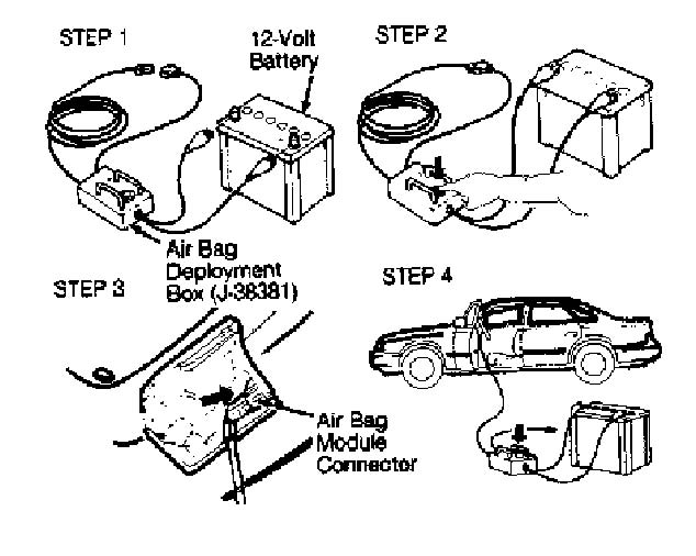
Fig. 4: Deploying Air Bag Module & Seat Belt Pretensioners Courtesy of Nissan Motor Co., U.S.A.
POST-COLLISION INSPECTION
Proper operation of SRS requires any repairs to vehicle structure return it to its original production configuration. Manufacturer recommends checking complete SRS for damage. Inspect all SRS components for dents, cracks, deformities or rust. Inspect steering wheel for noise, binding or heavy operation. Ensure air bag module(s) are fit and aligned properly. Replace SRS components as necessary. If air bag(s) and seat belt pretensioners deployed in collision, air bag module(s), seat belt pretensioners and control unit must be replaced. Always use NEW air bag module mounting bolts. After repairs are complete, check AIR BAG warning light to ensure system is functioning properly. See SYSTEM OPERATION CHECK.
REMOVAL & INSTALLATION
WARNING: Failure to follow air bag service precautions may result in
air bag deployment and personal injury. See SERVICE
PRECAUTIONS. After component replacement, perform a system
operational check to ensure proper system operation. See
SYSTEM OPERATION CHECK.
DRIVER’S AIR BAG MODULE & SPIRAL CABLE
Removal
1) Before proceeding, follow air bag service precautions. See SERVICE PRECAUTIONS. Disable Supplemental Restraint System (SRS). See DISABLING & ACTIVATING AIR BAG SYSTEM.
2) Driver’s air bag module is located on steering wheel hub. Remove lower lid (access cover) from steering wheel and disconnect air bag module connector. Spiral cable is located under steering wheel, in steering column.
3) Remove side access lids. Using a Torx T50H bit, remove and discard bolts from left and right sides of air bag module (steering wheel pad). Carefully remove air bag module. DO NOT drop or strike air bag module.
4) Before removing spiral cable, ensure steering wheel is in straight-ahead position. Disconnect horn connector, and remove nuts. Using steering wheel puller, remove steering wheel. DO NOT overtighten puller bolt on steering wheel.
5) Attach spiral cable to Spiral Cable Stopper (J-38378). Remove steering column cover. Unplug connector. Remove 4 screws and spiral cable. See Figs. 5 and 6.
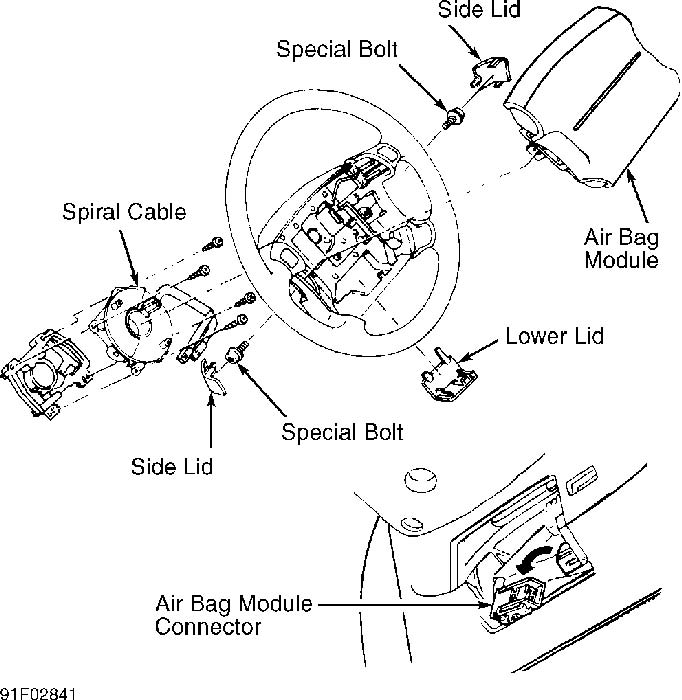
Fig. 5: Removing Driver’s Air Bag Module & Spiral Cable (Typical) Courtesy of Nissan Motor Co., U.S.A.
Installation
1) Connect spiral cable connector and tighten screws. Install steering column cover. Adjust and install spiral cable. See ADJUSTMENTS. Remove spiral cable stopper by pulling on 2-pin guides. Align spiral cable with steering wheel in straight-ahead position.
2) Install steering wheel, setting spiral cable pin guides, and pull spiral cable through. Connect horn connector, and engage
spiral cable with pawls in steering wheel. Tighten nuts. See Figs. 5 and 6.
3) Install air bag module. Tighten NEW bolts to 11-18 ft. lbs. (15-25 N.m). Connect air bag module connector. Install all access covers. Reactivate SRS. See DISABLING & ACTIVATING AIR BAG SYSTEM. Check AIR BAG indicator light to ensure system is functioning properly. See SYSTEM OPERATION CHECK.
CONTROL UNIT & SENSORS
Removal & Installation
1) Before proceeding, follow air bag service precautions. See SERVICE PRECAUTIONS. Disable air bag system. See DISABLING & ACTIVATING SRS.
2) On all vehicles, center impact sensor is located on center of vehicle front behind and below hood lock. See Figs. 1 and 2. On 300ZX, 2 additional front impact sensors are located on right side and left side of vehicle front. See Fig. 3.
3) On all vehicles, a tunnel sensor and safing (safety) sensor are located along transmission tunnel near middle of vehicle. Remove control unit or sensor(s). After removal, discard old bolts, which are coated with a special bonding agent.
4) To install, reverse removal procedure. Ensure sensor brackets are free of defects and rust. Install NEW sensors and control unit using NEW bolts. Tighten bolts to specification. See TORQUE SPECIFICATIONS TABLE at the end of this article.
5) Check sensors for proper installation (arrow marks facing front of vehicle). Reactivate air bag system. See DISABLING & ACTIVATING AIR BAG SYSTEM. Check AIR BAG indicator light to ensure system is functioning properly. See SYSTEM OPERATION CHECK.
ADJUSTMENTS
SPIRAL CABLE
1) Ensure front wheels face straight ahead when installing or removing a spiral cable assembly. If spiral cable is removed without wheels in straight-ahead position and steering wheel has not been moved, same spiral cable can be reinstalled provided spiral cable has not been rotated.
2) If centering of spiral cable is necessary, turn spiral cable clockwise until it catches stopper. Then back spiral cable off approximately 2 turns until Yellow alignment mark appears on left gear. See Fig. 6. Align ARROW on spiral cable with Yellow alignment mark.
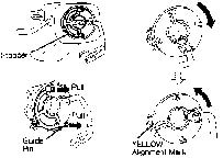
Fig. 6: Adjusting Spiral Cable Courtesy of Nissan Motor Co., U.S.A.
TORQUE SPECIFICATIONS
TORQUE SPECIFICATIONS TABLE
�������������������������������������������������������������������������������������������������������������
Application Ft. Lbs. (N.m)
Air Bag Module Bolts .................. 11-18 (15-25) Control Unit Bolts .................... 11-18 (15-25) Impact Sensor Bolts ................... 11-18 (15-25) Steering Wheel Nut .................... 22-29 (30-39)
�������������������������������������������������������������������������������������������������������������
WIRING DIAGRAMS
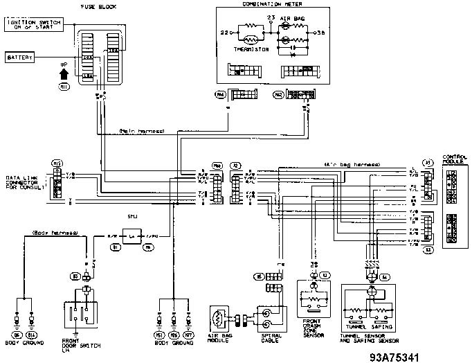
Fig. 7: SRS Wiring Diagram (Altima) Courtesy of Nissan Motor Co., U.S.A.
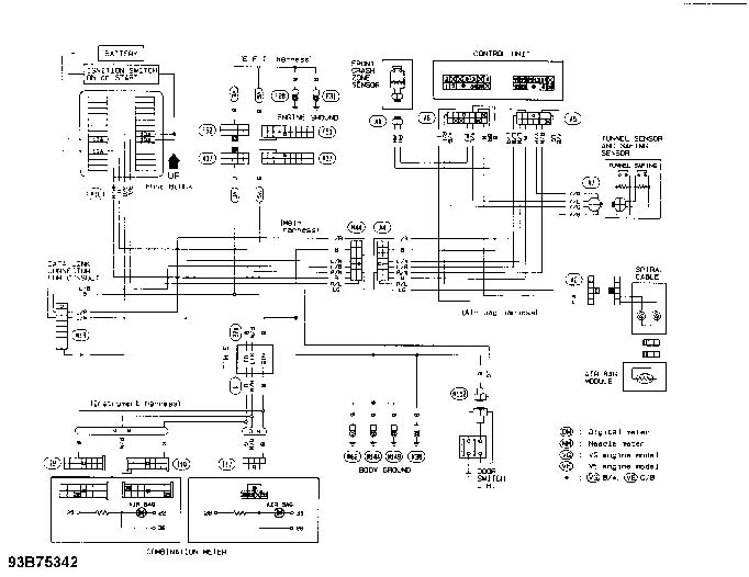
Fig. 8: SRS Wiring Diagram (Maxima) Courtesy of Nissan Motor Co., U.S.A.
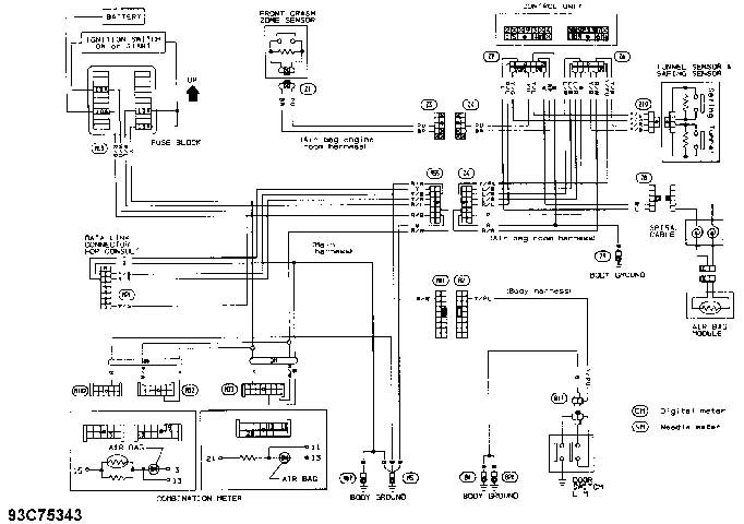
Fig. 9: SRS Wiring Diagram (NX & Sentra, Coupe) Courtesy of Nissan Motor Co., U.S.A.
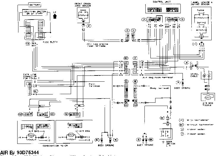
Fig. 10: SRS Wiring Diagram (NX & Sentra, Sedan) Courtesy of Nissan Motor Co., U.S.A.
DIAGNOSIS & TESTING
WARNING: Failure to follow SRS service precautions may result in SRS deployment and personal injury. See DISABLING & ACTIVATING SRS. After component replacement, perform a system operational check to ensure proper system operation. See SYSTEM OPERATION CHECK.
SELF-DIAGNOSTIC SYSTEM
Self-diagnostics can be performed by retrieving fault codes from SRS indicator light in instrument cluster or by using Nissan CONSULT unit. See DIAGNOSTIC PROCEDURES. After malfunctioning components have been repaired, return system to USER MODE. After repairing a malfunctioning component, clear self-diagnostic results from memory by disconnecting battery. If a malfunctioning component(s) is not completely repaired, information stored in memory will not be cleared.
DIAGNOSTIC PROCEDURES
Using Nissan CONSULT Unit
1) Turn ignition switch to ON or START position. SRS warning light should come on for about 7 seconds and then turn off, indicating system is operational. If SRS warning light flashes, go to next step. If SRS warning light does not come on or stays on, go to SRS WARNING LIGHT PROBLEMS under DIAGNOSTIC TESTS.
2) Connect CONSULT to data link connector located under driver’s side of instrument panel. Turn ignition switch to ON position. SRS warning light will be turned to PRESENT DIAGNOSIS MODE. Press START button to activate CONSULT unit. Press AIR BAG button. Press SELF DIAG RESULTS to read self-diagnostic results.
3) Fault codes will be displayed on SELF-DIAGNOSIS RESULTS 1 (first page - present mode). Fault code last indicated will be displayed on SELF-DIAGNOSIS RESULTS 2 (second page - initial mode). When PRINT button is pressed fault code information from SELFDIAGNOSIS RESULTS 1 and 2 will be printed out. See CONSULT FAULT MESSAGES table to diagnose SRS system.
4) After repairing or replacing defective components press ERASE button to clear SELF-DIAGNOSIS RESULTS. If fault code(s) do not completely clear from memory, repairs have not been completed. If fault code(s) do clear from memory, push BACK KEY of CONSULT until SELECT SYSTEM mode appears to return SELF-DIAGNOSIS to USER MODE.
CONSULT FAULT MESSAGES TABLE
�������������������������������������������������������������������������������������������������������������
Message 1) Fault Code
NO SELF DIAGNOSTIC
FAILURE ......................................... 0 SAFING SENSOR ..................................... 1
(OPEN/LWR-GND-SHORT)
(SHORT/LWR-VB-SHORT) AIRBAG MODULE ..................................... 2
(OPEN)
(VB-SHORT)
(GND-SHORT) TUNNEL SENSOR ..................................... 3
(OPEN/UPR-VB-SHORT)
(SHORT) CRASH ZONE SEN-RH (2) ............................. 4
(OPEN/UPR-VB-SHORT)
(SHORT) CRASH ZONE SEN-LH (2) ............................. 5
(OPEN/UPR-VB-SHORT)
(SHORT) CRASH ZONE SEN-CTR ................................ 6
(OPEN/UPR-VB-SHORT)
(SHORT) CONTROL UNIT ...................................... 7 INDEFINITE FAILURES ............................... 8
- (1)
- - Proceed to appropriate fault code under DIAGNOSTIC TESTS for corrective action.
- (2)
- - 300ZX only.
�������������������������������������������������������������������������������������������������������������
Using SRS Warning Light Flashes
1) Turn ignition switch to ON or START position. SRS warning light should come on for about 7 seconds and then turn off, indicating system is operational. If SRS warning light flashes, go to next step. If SRS warning light does not come on or stays on, go to SRS WARNING LIGHT PROBLEMS under DIAGNOSTIC TESTS.
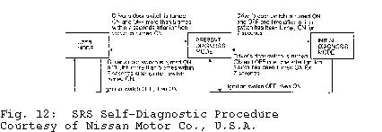
2) To activate SRS indicator light self-diagnostic, turn ignition switch to ON position. Within 7 seconds turn driver’s door/dome light switch on and off more than 5 times. See Fig. 12. Fault codes will be displayed in PRESENT DIAGNOSIS MODE. Fault code last indicated will be displayed in INITIAL DIAGNOSIS MODE. See appropriate SELF-DIAGNOSTIC SRS FAULT CODES to diagnose SRS system.
3) After repairing or replacing defective components return system to USER MODE to clear SELF-DIAGNOSIS RESULTS. If fault code(s) do not completely clear from memory, repairs have not been completed. See Fig. 12.
4) Fault code flashes are read when ignition switch is turned to ON position. Fault code flashes are identified as follows:
- *
- USER MODE System normal light will come on for 7 seconds and go off. System failure light will come on for 5 seconds and start a half second on and off cycle. If SRS has deployed or part of control unit is defective, light will come on and not go off.
- *
- PRESENT DIAGNOSIS MODE Start signal light will come on for approximately 5-7 seconds, off for 2 seconds, on for 3 seconds and off for 2 seconds. Fault codes light will then start a half second on and off cycle. See appropriate SELF-DIAGNOSTIC SRS FAULT CODES. If there is no fault, intermittent fault or repairs are completed light will come on for approximately 5-7 seconds, off for 2 seconds, on for 3 seconds, off for 2 seconds repeating on/off cycle.
- *
- INITIAL DIAGNOSIS MODE Start signal light will flash on and off rapidly 8 times. Before fault codes display light will be off for approximately 2 seconds, on for 1.5 seconds, off for .5 second, on for one second, off for 2 seconds. Light will flash fault codes and repeat predisplay flash cycle before repeating fault codes. See appropriate SELF-DIAGNOSTIC SRS FAULT CODES. Predisplay flash cycle will repeat if there are no fault codes.
DIAGNOSTIC TESTS
SRS WARNING LIGHT PROBLEMS
SRS Warning Light Does Not Come On
1) Check SRS warning light fuse, and replace if blown. If fuse is okay, use CONSULT unit to begin diagnosis. If AIR BAG displays, read SELF-DIAGNOSIS RESULTS 1 and 2. See SELF-DIAGNOSTIC SRS FAULT CODES to diagnose SRS system.
2) If AIR BAG does not display, replace control unit. If SELF-DIAGNOSIS RESULTS 1 and 2 are okay, check SRS warning light bulb and replace if necessary. If bulb is okay, check warning light harness connection and replace as necessary. If harness connection is okay, replace control unit.
SRS Warning Light Stays On
1) If Air Bag Module(s) has been deployed, replace Air Bag Module(s). If Air Bag Module(s) is okay, check SRS fuse and replace as necessary.
2) If fuse is okay, use CONSULT unit to begin diagnosis. If AIR BAG displays, read SELF-DIAGNOSIS RESULTS 1 and 2 and go to SELFDIAGNOSTIC SRS FAULT CODES to diagnose SRS system. If AIR BAG does not display, replace control unit. Using SRS warning light determine whether warning light is flashing a fault code. See SELF-DIAGNOSTIC SRS FAULT CODES. If warning light is not flashing a fault code, check harness connection between warning light and control unit. If harness connection is okay, replace control unit.
SELF-DIAGNOSTIC SRS FAULT CODES
NOTE: Self-diagnostic results can be obtained by using Nissan
CONSULT unit or counting SRS warning lamp flashes. See
DIAGNOSTIC PROCEDURES. It is important that corrective
actions are performed in order listed and SRS is rechecked
after each repair or component replacement. Wire colors and
terminal numbers apply to all models, unless otherwise
specified.
FAULT CODE 0, NO SELF-DIAGNOSTIC FAILURE
- *
- Possible Cause Normal, SRS is okay.
- *
- Corrective Action No corrective action necessary. FAULT CODE 1, SAFING SENSOR CIRCUIT IS DEFECTIVE
- *
- Possible Causes Safing sensor circuit is open or Yellow/Blue wire from safing sensor to control unit terminal No. 3 is shorted to ground. Both wires for safing sensor are shorted or Yellow/Blue wire from safing sensor to control unit terminal No. 3 is shorted to battery voltage.
- *
- Corrective Action Visually check wiring harness connections. Replace safing sensor and tunnel sensor as a unit. Replace control unit. Replace main harness.
FAULT CODE 2, DRIVER’S AIR BAG MODULE
Circuit Is Defective
| * | Possible Causes |
| White wire and Blue wire to air bag module and spiral | |
| cable has an open, is shorted to ground or is shorted to | |
| battery voltage. | |
| * | Corrective Action |
| Visually check harness connections. Replace spiral cable. | |
| Replace driver’s air bag module (SRS must be deployed | |
| before disposal). Replace control unit. Replace main | |
| harness. |
FAULT CODE 3, TUNNEL SENSOR CIRCUIT IS DEFECTIVE.
- *
- Possible Causes Yellow/Red wire and/or Yellow/Black wire are open or are shorted to each other. Yellow/Black wire from control unit terminal No. 6 to tunnel sensor is shorted to battery voltage.
- *
- Corrective Action Visually check harness connections. Replace safing sensor and tunnel sensor as a unit. Replace control unit. Replace main harness. FAULT CODE 4, RIGHT SIDE IMPACT SENSOR IS DEFECTIVE (300ZX)
- *
- Possible Causes Orange wire and Green wire to right side impact sensor is open or Green wire from control unit terminal No. 7 to right side impact sensor is shorted to battery voltage. Orange wire and Green wire for right side Impact sensor are shorted to each other.
- *
- Corrective Action Visually check harness connections. Replace right side impact sensor. Replace control unit. Replace main harness. FAULT CODE 5, LEFT SIDE IMPACT SENSOR IS DEFECTIVE (300ZX)
- *
- Possible Causes Light Green wire and Gray wire to left side impact sensor is open or Gray wire from control unit terminal No. 8 to left side impact sensor is shorted to battery voltage. Light Green wire and Gray wire for left side Impact sensor are shorted to each other.
- *
- Corrective Action Visually check harness connections. Replace left side impact sensor. Replace control unit. Replace main harness. FAULT CODE 6, CENTER IMPACT SENSOR CIRCUIT IS DEFECTIVE.
- *
- Possible Causes Purple wire and Brown wire to center impact sensor is open or Purple wire from control unit terminal No. 9 to center impact sensor is shorted to battery voltage. Purple wire and Brown wire for center Impact sensor are shorted to each other.
- *
- Corrective Action Visually check harness connections. Replace center impact sensor. Replace control unit. Replace main harness. FAULT CODE 7, CONTROL UNIT (DIAGNOSTIC UNIT) DEFECTIVE
- *
- Possible Cause Control unit (diagnostic unit) defective.
- *
- Corrective Action Visually check harness connections. Replace control unit. Replace main harness. FAULT CODE 8, MORE THAN 2 PARTS GROUPS ARE DEFECTIVE
- *
- Possible Cause A problem which cannot be specified occurs because more than 2 parts are defective.
- *
- Corrective Action Replace defective components listed from INITIAL DIAGNOSIS MODE (self-diagnosis result 2). Visually check harness connections. Replace control unit. Replace all sensors, spiral cable and air bag module. Replace main harness.
POST-COLLISION AIR BAG SAFETY INSPECTION
POST-COLLISION AIR BAG SAFETY INSPECTION TABLE
��������������������������������������������������������������������������������������������������������������������������������������� �� � �Replace After Deployment �* Air Bag Module(s) � ��* Control Unit �
�* Sensors In Affected Collision Area ������������������������������������������������������������������������������������������������������������������������������������� �� � �Inspect & If Damaged, �* All Sensors �
�Replace Component �* Spiral Cable � �(Even If Air Bag Did �* Steering Wheel �
�Not Deploy) * Wiring Harnesses
������������������������������������������������������������������������������������������������������������������������������������� �� � �Comments �* If any components are damaged or �
��bent, they must be replaced. � ��* DO NOT attempt SRS wiring harness �
� repairs. �������������������������������������������������������������������������������������������������������������������������������������