
�ALTERNATOR & REGULATOR -HITACHI
�1993 Nissan Sentra
1993 ELECTRICAL Nissan Alternators & Regulators - Hitachi
Altima, Maxima, NX, Pathfinder, Pickup, Sentra, 240SX, 300ZX
NOTE: If vehicle is equipped with Mitsubishi alternator, see ALTERNATOR & REGULATOR - MITSUBISHI article in the ELECTRICAL section.
DESCRIPTION
Conventional 3-phase, self-rectifying Hitachi alternator contains 3 positive and 3 negative diodes that rectify current. See Fig. 3. Regulator is inside alternator.
ADJUSTMENTS
BELT TENSION
ALTERNATOR BELT ADJUSTMENT
�������������������������������������������������������������������������������������������������������������������������������������������
Application (1) Deflection In. (mm)
Altima ............................................... .24-.28 (6-7)
Maxima (2) VE30DE ......................................... .29-.33 (7.5-8.5) VG30E .............................................. .28-.35 (7-9)
NX & Sentra 1.6L ............................................... .28-.35 (7-9) 2.0L (With A/C) .................................... .28-.31 (7-8) 2.0L (Without A/C) ................................. .31-.35 (8-9)
Pathfinder & Pickup 2.4L ............................................. .39-.47 (10-12) 3.0L ............................................... .24-.31 (6-8)
240SX ................................................ .28-.31 (7-8) 300ZX ................................................ .28-.31 (7-8)
- (1)
- - Deflection is with 22 lbs. (10 kg) pressure applied midway on the longest belt run.
- (2)
- - Vehicles with VE30DE engine use a distributorless ignition system. Vehicles with VG30E engine use a distributor.
�������������������������������������������������������������������������������������������������������������������������������������������
TROUBLE SHOOTING
NOTE: See TROUBLE SHOOTING - BASIC PROCEDURES article in GENERAL INFORMATION section.
ON-VEHICLE TESTING
NOTE: Before testing, ensure alternator wire harness connections are secure, drive belt tension is okay and battery is fully charged. After starting engine, wait at least 30 seconds before measuring voltage. Terminals "S", "L", "B", and "E" are marked on alternator’s rear cover. Terminal "F" is inside alternator.
Alternator Test
1) Turn ignition on. If charge indicator light on instrument panel comes on, go to step 3). If light is off, disconnect alternator connector (terminals "L" and "S"). Ground terminal "L". If light remains off, replace indicator bulb, reconnect alternator connector and recheck.
2) If light comes on, reconnect alternator connector. Full- field alternator by grounding internal terminal "F" with a wire. See Fig. 1. If light goes out, repair or replace alternator. If light is on, replace regulator.
3) Start and run engine at idle. If light is dim, flickers or remains on (bright), repair or replace alternator. If light goes out, operate engine at 1500 RPM and turn on headlights. If light comes on, replace regulator.
4) If light stays off, measure voltage at terminal "B" while running engine at 1500 RPM. If more than 15.5 volts are present, replace regulator. If 13-15 volts are present, alternator and regulator are okay. Ensure alternator output amperage is as specified. See HITACHI ALTERNATOR OUTPUT AMPERAGE SPECIFICATIONS table.
HITACHI ALTERNATOR OUTPUT AMPERAGE SPECIFICATIONS
�����������������������������������������������������������������������������������������������������������������������
Application Amps @ 2500 RPM Amps @ 5000 RPM
| Altima | ..................... | 66 | ..................... | 77 | ||
|---|---|---|---|---|---|---|
| Maxima (1) | ||||||
| VE30DE | ................... | 80 | ..................... | 91 | ||
| VG30E | .................... | 63 | ..................... | 84 | ||
| NX & Sentra | ||||||
| 1.6L | ..................... | 50 | ..................... | 67 | ||
| 2.0L | ..................... | 63 | ..................... | 77 | ||
| Pathfinder & Pickup | ||||||
| 2.4L | ..................... | 48 | ..................... | 57 | ||
| 3.0L | ..................... | 50 | ..................... | 67 | ||
| 240SX | ...................... | 63 | ..................... | 77 | ||
| 300ZX | ...................... | 65 | ..................... | 80 | ||
(1) - Vehicles with VE30DE engine use a distributorless ignition system. Vehicles with VG30E engine use a distributor.
�����������������������������������������������������������������������������������������������������������������������
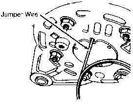
Fig. 1: Full-Fielding Hitachi Alternator Courtesy of Nissan Motor Co., U.S.A.
BENCH TESTING
Rotor
Connect one ohmmeter lead to each rotor slip ring. If resistance is about 2-3 ohms, rotor is okay. If about 2-3 ohms resistance is not present, rotor is defective. Connect an ohmmeter lead to any rotor slip ring, and connect remaining lead to rotor core. If continuity exists, replace rotor assembly.
MINIMUM SLIP RING DIAMETER
�����������������������������������������������������������������������������������������������������������������������
Application In. (mm)
Maxima & 300ZX .................................. 1.0 (26) All Others .................................... 1.2 (30.5)
�����������������������������������������������������������������������������������������������������������������������
NOTE: To test stator or diodes, separate them by unsoldering
connecting wires. Use just enough heat to melt solder.
Excess heat will damage diodes.
Stator
Using ohmmeter, check continuity between stator core leads. If continuity is not present between leads, replace stator. Connect an ohmmeter lead to stator core. Connect remaining ohmmeter lead, in turn, to each of the stator leads. If continuity is not present, stator is good. If continuity exists, stator is grounded. Replace stator.
Diodes
Using an ohmmeter, check continuity of all diodes in both directions. Ensure continuity exists in only one direction. See ALTERNATOR DIODES TEST table. See Fig. 2. If continuity exists in both directions, diode is shorted. If continuity is not present in either direction, diode is open. If any diode is defective, replace entire diode assembly.
ALTERNATOR DIODES TEST
�����������������������������������������������������������������������������������������������������������������������
Positive Meter Lead Negative Meter Lead Continuity
| (+) Diode Plate | ........ | Diode Terminals | ........... | Yes |
| Diode Terminals | ........ | (+) Diode Plate | ............ | No |
| (-) Diode Plate | ........ | Diode Terminals | ............ | No |
| Diode Terminals | ........ | (-) Diode Plate | ........... | Yes |
�����������������������������������������������������������������������������������������������������������������������
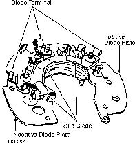
Fig. 2: Testing Diode Assembly Courtesy of Nissan Motor Co., U.S.A.
Brushes
Inspect brushes for freedom of movement in holder. Clean brush holder if necessary. Check brushes for cracks and wear. Check brush springs for corrosion or damage. Ensure brushes are not worn beyond minimum length. See MINIMUM BRUSH LENGTH table.
MINIMUM BRUSH LENGTH
�����������������������������������������������������������������������������������������������������������������������
Application In. (mm)
Maxima With Distributor & 300ZX .................. .28 (7) All Others ....................................... .24 (6)
�����������������������������������������������������������������������������������������������������������������������
OVERHAUL
NOTE: A ring is used to lock outer bearing race in alternator’s rear cover. It may be necessary to heat bearing housing to remove cover. Use a 200-watt soldering iron to heat housing. DO NOT use heat gun as it may damage diode. For exploded view of alternator, see Fig. 3.
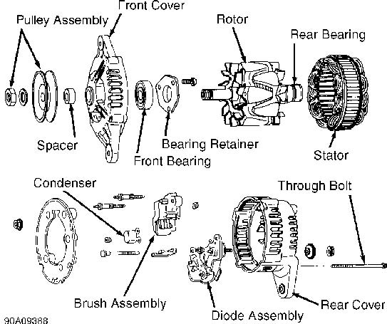
Fig. 3: Exploded View Of Typical Hitachi Alternator Courtesy of Nissan Motor Co., U.S.A.
WIRING DIAGRAMS
Proceed to appropriate WIRING DIAGRAM article listed below in WIRING DIAGRAMS section.
- *
- WIRING DIAGRAMS (for Altima).
- *
- WIRING DIAGRAMS (for Maxima).
- *
- WIRING DIAGRAMS (for NX).
- *
- WIRING DIAGRAMS (for Pathfinder).
- *
- WIRING DIAGRAMS (for Pickup).
- *
- WIRING DIAGRAMS (for Sentra).
- *
- WIRING DIAGRAMS (for 240SX).
- *
- WIRING DIAGRAMS (for 300ZX).