�ANTI-LOCK BRAKE SYSTEM
�1993 Nissan Sentra
1993 BRAKES Nissan Anti-Lock
NX & Sentra
DESCRIPTION
Anti-Lock Brake System (ABS) allows the driver to maintain steering control during heavy braking by fluctuating brakeline pressure. System consists of an Electronic Control Unit (ECU) with LED (for diagnostic usage), wheel speed sensors, actuator (electrohydraulic unit) and an ANTI-LOCK warning light located in dash. See Fig. 1.
ANTI-LOCK warning light comes on to warn driver of problem in ABS. LED on ECU will flash (indicating trouble codes) when warning light is illuminated.
NOTE: For more brake system information, see appropriate DISC & DRUM article in this section.
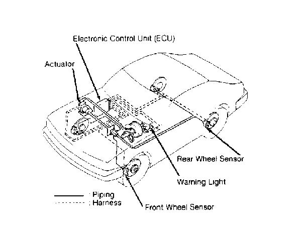
Fig. 1: Locating Anti-Lock Brake System (ABS) Components Courtesy of Nissan Motor Co., U.S.A.
OPERATION
As vehicle is moving, each wheel speed sensor sends an AC signal to the ECU. When brake pedal is applied, ECU receives signal through stoplight switch. When this occurs, ECU will monitor deceleration rate of wheels through wheel speed sensors. One sensor is located on each wheel.
If deceleration rate from any speed sensor reaches a preprogrammed rate, ECU activates solenoid valves inside actuator (electro-hydraulic unit). Solenoid valves are cycled to apply, release or maintain hydraulic pressure to each brake caliper depending upon signals from ECU. Regulating hydraulic pressure to each caliper prevents wheel lock-up.
When brake pedal is released, ECU will deactivate solenoid valves, and system will return to conventional brake system operation until ABS is again needed.
CAUTION: See ANTI-LOCK BRAKE SAFETY PRECAUTIONS in this article.
ANTI-LOCK BRAKE SAFETY PRECAUTIONS
- *
- NEVER open a bleeder valve or loosen a hydraulic line while ABS is pressurized
- *
- NEVER disconnect or reconnect any electrical connectors while ignition is on. Damage to ABS control unit may result.
- *
- DO NOT attempt to bleed hydraulic system without first referring to the appropriate article.
- *
- Only use specially designed brake hoses/lines on ABS-equipped vehicles.
- *
- DO NOT tap on speed sensor components (sensor, sensor rings). Speed rings must be pressed, NOT hammered into hubs. Striking these components can cause demagnetization or a loss of polarization, affecting the accuracy of the speed signal returning to the ABS control unit.
- *
- DO NOT mix tire sizes. Increasing the width, as long as tires remain close to the original diameter, is acceptable. Rolling diameter must be identical for all 4 tires. Some manufacturers recommend tires of the same brand, style and type. Failure to follow this precaution may cause inaccurate wheel speed readings.
- *
- DO NOT contaminate speed sensor components with grease. Only use recommended anti-corrosion coating.
- *
- When speed sensor components have been removed, ALWAYS check sensor-to-ring air gaps when applicable. These specifications can be found in each appropriate article.
- *
- ONLY use recommended brake fluids. DO NOT use silicone brake fluids in an ABS-equipped vehicle.
- *
- When installing transmitting devices (CB’s, telephones, etc.) on ABS-equipped vehicles, DO NOT locate the antenna near the ABS control unit (or any control unit).
- *
- Disconnect all on-board computers, when using electric welding equipment.
- *
- DO NOT expose the ABS control unit to prolonged periods of
��
high heat (185 F/85 C for 2 hours is generally considered a maximum limit).
BLEEDING BRAKE SYSTEM
To bleed brake system, unplug electrical connectors from actuator. Bleed brake system in a conventional manner using the following sequence: left rear caliper, right front caliper, right rear caliper, left front caliper, front air bleeder on ABS actuator and rear air bleeder on ABS actuator.
ADJUSTMENTS
BRAKE PEDAL HEIGHT & FREE PLAY
Pull back carpet and insulator. Measure pedal height from pressure face of pedal pad to floor pan melt sheet. If pedal height is not as specified, loosen brake booster input rod lock nut. See BRAKE PEDAL HEIGHT SPECIFICATIONS table. Rotate input rod to obtain proper height. Tighten lock nut. Adjust stoplight switch. Ensure pedal free play is .04-.12" (1-3 mm).
BRAKE PEDAL HEIGHT SPECIFICATIONS TABLE
�������������������������������������������������������������������������������������������������������������
Pedal Height
| Application | In. (mm) | ||
| Automatic Transaxle | ............... | 6.2-6.6 (157-167) | |
| Manual Transaxle | .................. | 5.8-6.2 (148-158) | |
�������������������������������������������������������������������������������������������������������������
PARKING BRAKE
Raise and support rear of vehicle. Remove parking brake lever cover. Loosen parking brake cable adjusting nut at base of lever. Press brake pedal at least 5 times to remove slack in rear brakes. Pull parking brake lever 4-5 notches. Tighten parking brake lever adjusting nut until lever moves 7-8 notches with 44 lbs. (20 kg) of force applied to lever. Release lever. Ensure rear wheels rotate freely.
POWER BRAKE UNIT OUTPUT ROD
Apply 20 in. Hg vacuum to power brake unit with hand-held vacuum pump. See Fig. 2. Measure length of output rod extending from power brake unit housing. Adjust output rod if length is not .40-.41" (10.3-10.5 mm). If length cannot be adjusted, replace power brake unit.
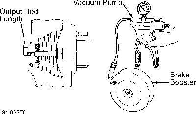
Fig. 2: Measuring Output Rod Length Courtesy of Nissan Motor Co., U.S.A.
STOPLIGHT & CRUISE CONTROL SWITCHES
Switches are on brake pedal bracket. Adjust brake pedal height. See BRAKE PEDAL HEIGHT & FREE PLAY under ADJUSTMENTS. If clearance between brake pedal stopper and switch is not .004-.012" (. 10-.30 mm), loosen lock nut. Turn switch body until clearance is as specified. Tighten lock nut.
TROUBLE SHOOTING
ANTI-LOCK WARNING LIGHT
System Operational Check
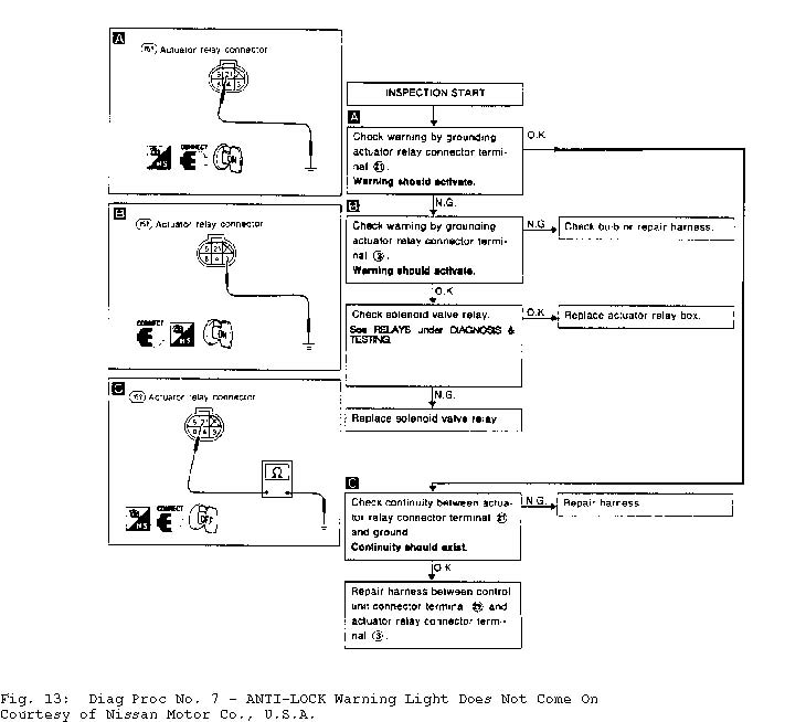
1) Turn ignition on. If ANTI-LOCK warning light on instrument cluster does not come on, go to DIAGNOSTIC PROCEDURE NO. 7. See Fig. 13. If light comes on, start engine. If light remains on after starting engine, go to RETRIEVING CODES under DIAGNOSIS & TESTING.
2) If light goes off after starting engine, drive vehicle at 19 MPH or faster for at least one minute. If light remains off, no fault has been detected by ECU. If light comes on during road test, go to RETRIEVING CODES under DIAGNOSIS & TESTING.
3) If light does not come on after engine is started and a problem exists, diagnose by symptom. See SYMPTOMS under TROUBLE SHOOTING.
SYMPTOMS
Pedal Vibration/Noise See Fig. 7.
Long Stopping Distance See Fig. 8.
Abnormal Pedal Action See Fig. 9.
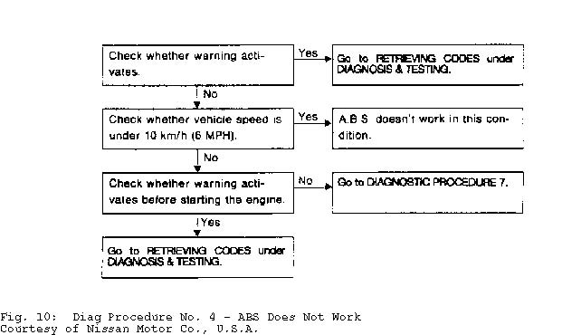
ABS Does Not Work See Fig. 10.
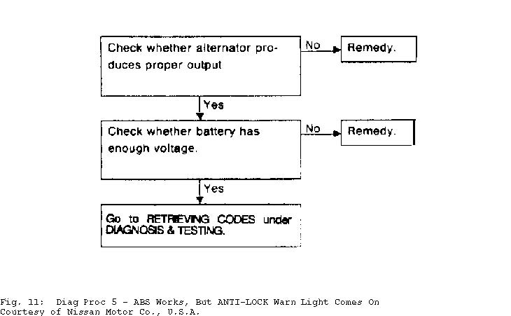
ABS Works, But ANTI-LOCK Light Comes On See Fig. 11.
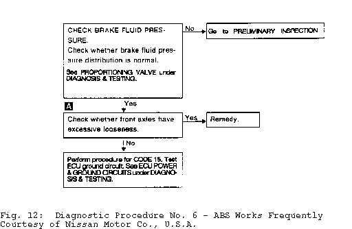
ABS Works Frequently See Fig. 12.
ANTI-LOCK Light Does Not Come On See Fig. 13.
ANTI-LOCK Light Comes On, But LED Does Not Flash See ECU POWER & GROUND CIRCUITS under DIAGNOSIS & TESTING.
DIAGNOSIS & TESTING
* PLEASE READ THIS FIRST *
NOTE: To prevent terminal damage, backprobe terminals when connecting test meter leads to ECU connector. Testing actuator requires use of ABS Tester (KV999P1000) and Adapter (KV999P1010).
PRELIMINARY INSPECTION
Before performing self-diagnostics of ABS, check master
cylinder fluid level, locate and eliminate any fluid leaks, check power brake unit operation, and check brake pad and rotor condition.
RETRIEVING CODES
If codes are stored in ECU memory, ANTI-LOCK warning light on instrument cluster will come on. To retrieve codes, observe LED on ECU. See Fig. 1. Count number of flashes. LED pauses for 5-10 seconds before repeating code. See Fig. 3. See ABS WARNING CODE DIRECTORY table. LED displays only one code at a time. After problem circuit has been repaired, LED will display any remaining codes.
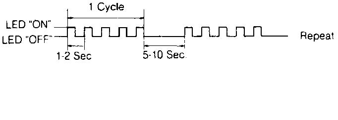
Fig. 3: Identifying Codes By Counting LED Flashes Courtesy of Nissan Motor Co., U.S.A.
ABS WARNING CODE DIRECTORY
�����������������������������������������������������������������������������������������������������������������������
Code Circuit See Fig.
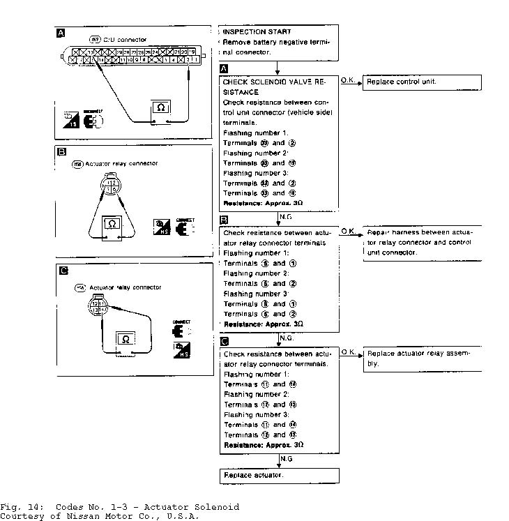
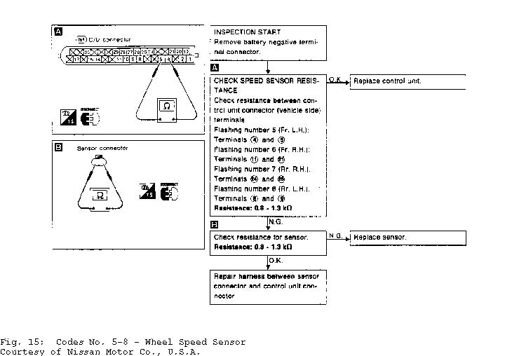
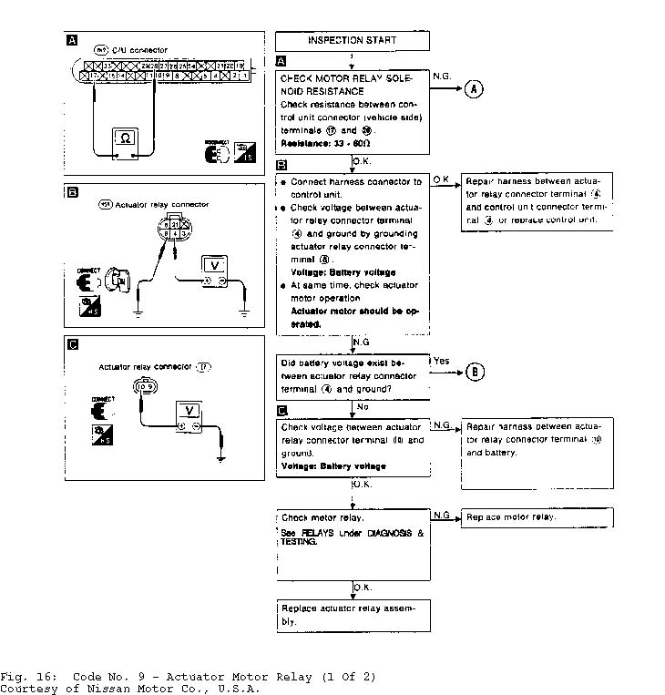
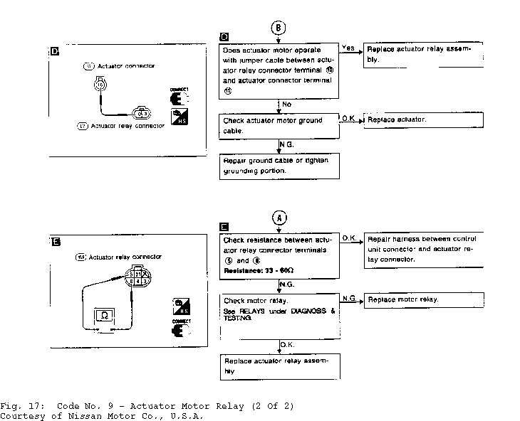
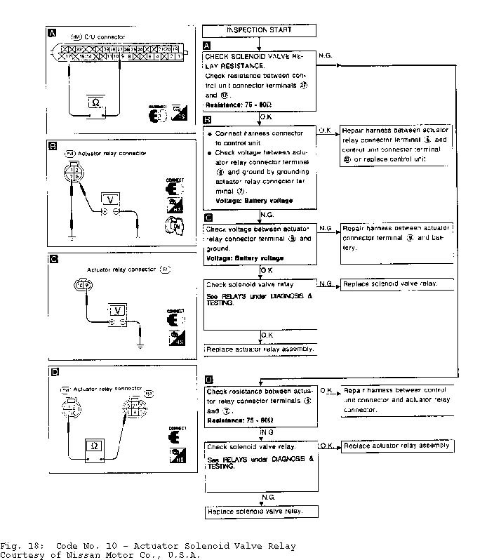
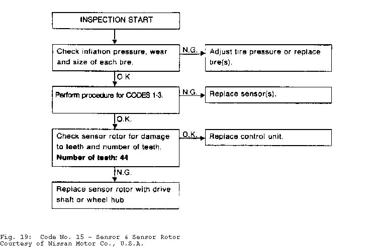
1 .............. L/F Actuator Solenoid ............... 14 2 .............. R/F Actuator Solenoid ............... 14 3 .............. Both Actuator Solenoids .............. 14 5 ................ L/F Speed Sensor .................. 15 6 ................ R/F Speed Sensor .................. 15 7 ................ R/R Speed Sensor .................. 15 8 ................ L/R Speed Sensor .................. 15 9 ........... Actuator Motor/Motor Relay ........ 16 & 17 10 ............. Solenoid Valve Relay ................ 18 15 ................ Sensor Rotor .................... 19 16 ................ Control Unit .................. (1)
(1) - Replace ABS control unit.
�����������������������������������������������������������������������������������������������������������������������
ECU POWER & GROUND CIRCUITS
CAUTION: Before servicing ECU, ground yourself and work area to
discharge stored electricity. As little as a 30-volt charge
created by static electricity can cause a total or degrading
failure in ECU or other electronic components containing
integrated circuits.
Power Circuit 1) Disconnect ECU connector. Turn ignition on. Check for
battery voltage on ECU connector terminal No. 1. See Fig. 4. If battery voltage is not present, repair circuit as necessary. If battery voltage is present, start engine.
2) Check voltage on ECU connector terminal No. 15. If 6 or more volts is present, power circuit is okay. If less than 6 volts is present, check circuit between ECU and alternator connector terminal "L" (Yellow/Red wire). If circuit is okay, repair or replace alternator.
Ground Circuit
Turn ignition off. Disconnect ECU connector. Using an ohmmeter, check for continuity between ground and ECU connector terminal No. 20. See Fig. 4. If there is no continuity, repair open in Black wire between ground and ECU connector terminal No. 20. If there is continuity, ground circuit is okay.
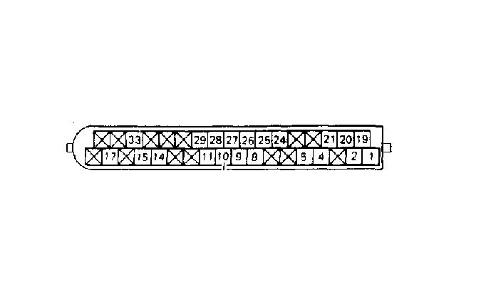
Fig. 4: Identifying ECU Connector Terminals Courtesy of Nissan Motor Co., U.S.A.
PROPORTIONING VALVE
NOTE: Carefully monitor master cylinder fluid level while testing proportioning valve.
Pressure Testing
1) Attach one pressure gauge to front brake bleeder and one pressure gauge to rear brake bleeder. Bleed air from front and rear bleeders.
2) Press brake pedal until front brake pressure reading is as specified. See PROPORTIONING VALVE PRESSURE SPECIFICATIONS table. Check rear brake pressure. If rear brake pressure is not within
specification, replace proportioning valve. PROPORTIONING VALVE PRESSURE SPECIFICATIONS TABLE
�������������������������������������������������������������������������������������������������������������������������������������������
| Front Brake Pressure | Rear Brake Pressure | |||||
|---|---|---|---|---|---|---|
| � | � | |||||
| Application | psi (kg/cm ) | psi (kg/cm ) | ||||
| Except 2.0L (SE) | ........... | 711 (50) | ............ | 284-341 (20-24) | ||
2.0L (SE) .................. 924 (64) ............ 498-555 (34-38)
�������������������������������������������������������������������������������������������������������������������������������������������
RELAYS
Actuator Motor Relay
Relay (metal body) is mounted on right front strut tower. Continuity should not be present between relay terminals No. 3 and 4. See Fig. 5. Apply battery voltage between terminals No. 1 and 2. Continuity should now be present between terminals No. 3 and 4.
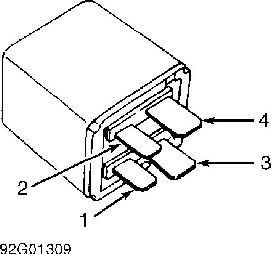
Fig. 5: Identifying Actuator Motor Relay Terminals Courtesy of Nissan Motor Co., U.S.A.
Solenoid Valve Relay Relay (Light Blue body) is mounted on right front strut
tower. Continuity should be present between relay terminals No. 30 and 87A. Continuity should not be present between terminals No. 30 and 87. See Fig. 6. Apply battery voltage between terminals No. 85 and 86. Continuity should not be present between terminals No. 30 and 87A. Continuity should be present between terminals No. 30 and 87.
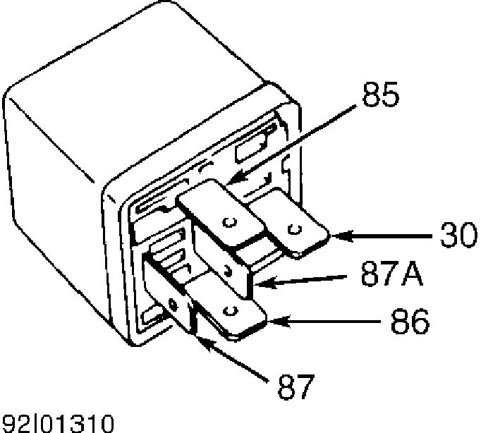
Fig. 6: Identifying Solenoid Valve Relay Terminals Courtesy of Nissan Motor Co., U.S.A.
WHEEL SPEED SENSOR
Resistance Test
Disconnect sensor connector at wheel. Using an ohmmeter, check resistance across sensor connector terminals. If resistance is not 800-1300 ohms, replace sensor.
TROUBLE SHOOTING CHARTS
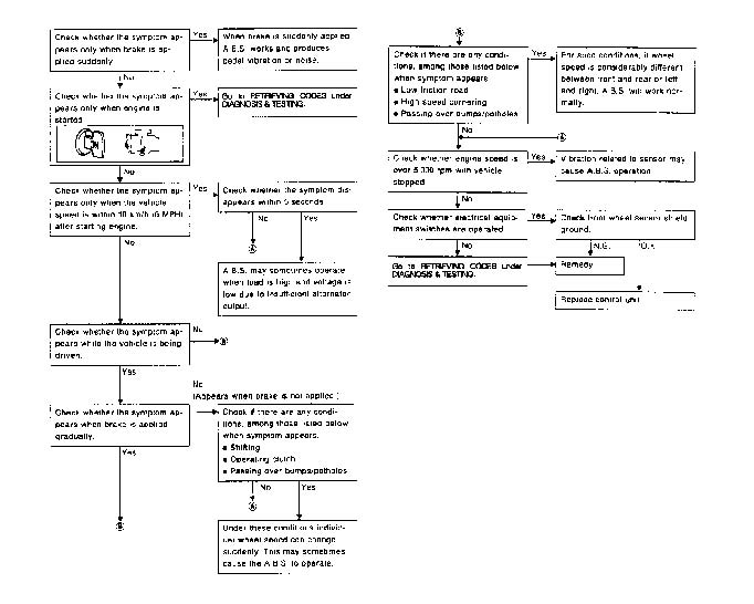
Fig. 7: Diag Procedure No. 1 - Pedal Vibration/Noise Courtesy of Nissan Motor Co., U.S.A.
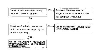
Fig. 8: Diag Procedure No. 2 - Long Stopping Distance Courtesy of Nissan Motor Co., U.S.A.
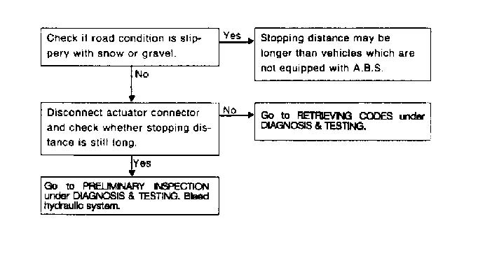
Fig. 9: Diag Procedure No. 3 - Abnormal Pedal Action Courtesy of Nissan Motor Co., U.S.A.
SELF-DIAGNOSTIC CHARTS
REMOVAL & INSTALLATION
ACTUATOR
Removal
1) Disconnect battery negative cable. Drain brake fluid from bleeder at each caliper. Drain power steering fluid. Discharge A/C system using approved refrigerant recovery/recycling equipment. Disconnect power steering pipe and hose.
2) Disconnect electrical connectors from actuator relay bracket. Remove relay bracket nut. Remove mounting bolt located under relay. Remove actuator relay box and bracket. Disconnect A/C hoses.
3) Disconnect upper 2 brakelines from actuator (lines from master cylinder). Remove 2 brakelines between actuator and proportioning valve. Remove actuator mounting nuts and grounding bolt. Remove actuator.
Installation
To install, reverse removal procedure. Install relay bracket before installing actuator relay box. Fill and bleed brake hydraulic system. See BLEEDING BRAKE SYSTEM. Evacuate and charge A/C system. Fill and bleed power steering hydraulic system by turning steering wheel from lock to lock.
ELECTRONIC CONTROL UNIT (ECU)
CAUTION: Before servicing ECU, ground yourself and work area to discharge stored electricity. As little as a 30-volt charge created by static electricity can cause a total or degrading failure in ECU or other electronic components containing integrated circuits.
Removal & Installation
Disconnect battery negative cable. Remove right kick panel. Disconnect ECU connector. See Fig. 1. Remove bolts and ECU. To install, reverse removal procedure.
WHEEL SPEED SENSOR & ROTOR
Removal & Installation
To remove sensor, remove sensor retaining bolt. Remove sensor. To remove sensor rotor, remove axle hub assembly. To install components, reverse removal procedure.
TORQUE SPECIFICATIONS
TORQUE SPECIFICATIONS TABLE
�����������������������������������������������������������������������������������������������������������������������
Application Ft. Lbs. (N.m)
Hydraulic Brakelines At Actuator ........... 12-14 (16-19) Wheel Lug Nuts ............................ 72-87 (98-118)
INCH Lbs. (N.m)
Actuator Mounting Nut ..................... 96-132 (11-15) Wheel Speed Sensor Mounting Bolt .......... 96-132 (11-15)
�����������������������������������������������������������������������������������������������������������������������
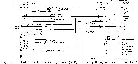
WIRING DIAGRAM