
�F -BASIC TESTING
�1993 Nissan Sentra
1993 ENGINE PERFORMANCE Nissan - Basic Diagnostic Procedures
Altima, Maxima, NX, Pathfinder, Pickup, Quest, Sentra, 240SX, 300ZX
INTRODUCTION
| NOTE: | Maxima 3.0L 12-valve engine is referred to as VG30E. Maxima 3.0L 24-valve engine is referred to as VE30DE. |
| NOTE: | Perform all voltage tests using a Digital Volt-Ohmmeter (DVOM) with a minimum 10-megohm input impedance, unless stated otherwise in test procedure. |
| The following diagnostic steps will help prevent overlooking |
a simple problem. This is also where to begin diagnosis for a no-start condition.
The first step in diagnosing any driveability problem is verifying the customer’s complaint with a test drive under the conditions the problem reportedly occurred. Before entering self- diagnostics, perform a careful and complete visual inspection. Most engine control problems result from mechanical breakdowns, poor electrical connections or damaged/misrouted vacuum hoses. Before condemning the computerized system, perform each test listed in this article.
PRELIMINARY INSPECTION & ADJUSTMENTS
VISUAL INSPECTION
Visually inspect all electrical wiring. Look for chafed, stretched, cut or pinched wiring. Ensure electrical connectors fit tightly and are not corroded. Ensure vacuum hoses are properly routed and not pinched or cut. See M - VACUUM DIAGRAMS article to verify routing and connections if necessary. Inspect air induction system for possible vacuum leaks.
MECHANICAL INSPECTION
WARNING: DO NOT use ignition switch during compression tests on fuel injected engines. Use a remote starter to crank engine. Fuel injectors on many models are triggered by ignition switch during cranking mode, which can create fire hazard and contaminate engine oiling system.
Compression
Check engine mechanical condition using a compression gauge, vacuum gauge or an engine analyzer. See engine analyzer manual for specific instructions.
4-CYLINDER COMPRESSION SPECIFICATIONS TABLE
���������������������������������������������������������������������������������������������������������������������������
Application Specification
Normal Compression Pressure� Altima .............................. 178 psi (12.5 kg/cm ) NX & Sentra
1.6L ................................ 192 psi (13.5 kg/cm � ) 2.0L ................................ 178 psi (12.5 kg/cm � ) Pickup .............................. 192 psi (13.5 kg/cm � ) 240SX ............................... 179 psi (12.6 kg/cm � )
Minimum Compression Pressure� Altima .............................. 149 psi (10.5 kg/cm ) NX & Sentra 1.6L ................................ 164 psi (11.5 kg/cm �� ) 2.0L ................................ 149 psi (10.5 kg/cm �) Pickup .............................. 142 psi (10.0 kg/cm �) 240SX ............................... 151 psi (10.6 kg/cm )
Maximum Variation Between Cylinders� All Models ............................ 14 psi (1.0 kg/cm )
���������������������������������������������������������������������������������������������������������������������������
V6 COMPRESSION SPECIFICATIONS TABLE
���������������������������������������������������������������������������������������������������������������������������
Application Specification
Normal Compression Pressure Maxima VE30DE .............................. 183 psi (12.9 kg/cm�� ) VG30E ............................... 173 psi (12.2 kg/cm �) Pathfinder, Pickup & Quest .......... 173 psi (12.2 kg/cm ) 300ZX Non-Turbo ........................... 186 psi (13.1 kg/cm �� ) Turbo ............................... 171 psi (12.0 kg/cm )
Minimum Compression Pressure (1) Maxima VE30DE .............................. 142 psi (10.0 kg/cm � ) VG30E ................................ 128 psi (9.0 kg/cm � ) Pathfinder, Pickup & Quest ........... 128 psi (9.0 kg/cm � ) 300ZX Non-Turbo ........................... 142 psi (10.0 kg/cm � ) Turbo ................................ 128 psi (9.0 kg/cm � )
Maximum Variation Between Cylinders All Models ............................ 14 psi (1.0 kg/cm � )
(1) - Minimum compression at 300-350 RPM.
���������������������������������������������������������������������������������������������������������������������������
Exhaust System Backpressure
Exhaust system can be checked using a vacuum or pressure gauge. If using a pressure gauge, remove O2 sensor or air injection check valve (if equipped). Connect a 0-5 psi pressure gauge. Run engine at 2500 RPM. If exhaust system backpressure is greater than 1 3/4-2 psi (.12-.14 kg/cm � ), exhaust system or catalytic converter is plugged.
If using a vacuum gauge, connect vacuum gauge hose to intake manifold vacuum port. Start engine. Observe vacuum gauge. Open throttle part way and hold steady. If vacuum gauge reading slowly drops after stabilizing, check exhaust system for a restriction.
FUEL SYSTEM
FUEL PRESSURE
Begin basic diagnosis of fuel system by determining fuel system pressure. If fuel pump is inoperative, check fuel pump fuse. If fuse is okay, see FUEL SYSTEM in I - SYS/COMP TESTS article. See L -WIRING DIAGRAMS article for specific circuit or wire color.
WARNING: Always relieve fuel pressure before disconnecting any fuel injection-related component. DO NOT allow fuel to contact engine or electrical components. If connecting fuel pressure gauge to fuel system without using a "T" connector, DO NOT operate fuel pump for more than a few seconds. Operating fuel pump longer than a few seconds under this condition can damage fuel pump.
1) To relieve fuel system pressure, remove fuel pump fuse (fuel pump relay on 300ZX). Start engine, and allow it to run until it stalls. Crank engine 2 or 3 more times to verify all pressure has dissipated.
2) Turn ignition off. Install fuel pump fuse or relay. Connect fuel gauge between fuel filter outlet and fuel tube using a "T" connector. Disconnect electrical connector at fuel pressure regulator control solenoid valve (if equipped).
3) Start engine. Check fuel line connections for leaks. Check fuel pressure with engine idling. Disconnect vacuum hose from pressure regulator. Recheck fuel pressure.
4) Compare fuel pressure readings on pressure gauge with specifications in FUEL PRESSURE table. Release fuel system pressure as described in step 1). Disconnect fuel pressure gauge. Reconnect fuel lines. Start engine and check for fuel leaks.
FUEL PRESSURE TABLE
�������������������������������������������������������������������������������������������������������������������������
At Idle At Idle W/O Vacuum W/Vacuum
��
| Application | psi (kg/cm | ) | psi (kg/cm | ) | |||||||
|---|---|---|---|---|---|---|---|---|---|---|---|
| Altima, Quest & 240SX | ...... | 43 (3.0) | .......... | 34 (2.4) | |||||||
| Maxima | ..................... | 44 (3.1) | .......... | 36 (2.5) | |||||||
| NX, Sentra & 300ZX | ......... | 43 (3.0) | .......... | 36 (2.5) | |||||||
| Pathfinder & Pickup | |||||||||||
| 4-Cylinder | ................ | 43 (3.0) | .......... | 33 (2.3) | |||||||
| V6 | ........................ | 43 (3.0) | .......... | 34 (2.4) | |||||||
�������������������������������������������������������������������������������������������������������������������������
IGNITION CHECKS
NOTE: Maxima VE30DE and 300ZX use distributorless ignition system.
DISTRIBUTOR IGNITION
To determine cause of no-spark condition, perform following tests in order given. Deviation from this procedure may cause false diagnosis and replacement of non-defective components.
Spark
Check for spark at coil wire and each spark plug wire using spark tester. DO NOT crank engine continuously for more than 2 seconds. Inspect secondary coil wire for arcing while testing spark at plugs. Check electrical connections at Crankshaft Position (CKP) sensor, ignition coil and power transistor.
Ignition Coil Power Source
1) Disconnect ignition coil 2-pin connector. Turn ignition on. Check for voltage at specified wire terminal. See IGNITION COIL POWER SOURCE TERMINAL IDENTIFICATION table.
2) If voltage is present, go to POWER TRANSISTOR. If voltage is not present, check continuity of entire circuit between battery and ignition coil, including fuse link and ignition switch.
IGNITION COIL POWER SOURCE TERMINAL IDENTIFICATION TABLE
���������������������������������������������������������������������������������������������������������������������
Application Wire Color
Altima & Quest .................................... Green NX & Sentra ................................ Green/Yellow Maxima ...................................... White/Green Pathfinder & Pickup ......................... Black/White 240SX ................................. Light Green/Black
���������������������������������������������������������������������������������������������������������������������
Power Transistor
For power transistor system testing, see appropriate CODE 21 (NO IGNITION REFERENCE) in G - TESTS W/CODES article. For power transistor component testing, see IGNITION SYSTEMS in appropriate I -SYS/COMP TESTS article.
Ignition Coil Resistance
1) If ignition coil malfunction is suspected, carefully inspect external housing for burned spots indicating secondary circuit arcing to primary or ground circuits. Disconnect ignition coil primary 2-pin connector.
2) Using an ohmmeter, check resistance between primary connector terminals. Check resistance between secondary tower and positive terminal of coil primary connector. Positive terminal is identified by wire color in IGNITION COIL POWER SOURCE TERMINAL IDENTIFICATION table. If either resistance is not as specified, replace ignition coil. See appropriate IGNITION COIL RESISTANCE table.
4-CYLINDER IGNITION COIL RESISTANCE TABLE - Ohms @ 68 � F (20 � C) �����������������������������������������������������������������������������������������������������������������������������
Application Primary Secondary
Altima & 240SX ................ 1.0 ................ 10,000
NX & Sentra
1.6L ......................... .9 ................. 13,000 2.0L ......................... 1.0 ................ 10,000 Pickup ........................ .7 .................... (1)
(1) - Secondary resistance cannot be read on Pickup.
�����������������������������������������������������������������������������������������������������������������������������
V6 IGNITION COIL RESISTANCE TABLE - Ohms @ 68 � F (20 � C) �����������������������������������������������������������������������������������������������������������������������������
Application Primary Secondary
Maxima (VG30E) ................ 1.0 ........... 8200-12,400 Pathfinder, Pickup & Quest .... 1.0 ................ 10,000
�����������������������������������������������������������������������������������������������������������������������������
Crankshaft Position (CKP) Sensor
1) CKP sensor is located inside distributor. If a fault is present in CKP sensor, Code 11 may be set in ECM memory. If Code 11 is set, perform appropriate CODE 11 (CKP SENSOR) in G - TESTS W/CODES article.
2) To test CKP sensor, remove distributor. Leave wiring harness connected. Using a voltmeter, connect negative lead to ground and alternately connect positive lead to 1-degree signal terminal and 120/180-degree signal terminal. See CKP SENSOR INPUT SIGNAL TERMINALS table. See Figs. 1-3.
3) Measure voltages at both terminals while rotating distributor by hand. Voltage should fluctuate 0-5 volts. If either
voltage signal does not fluctuate 0-5 volts, check harness for short or open circuit. If no problems are found, replace CKP sensor.
CKP SENSOR INPUT SIGNAL TERMINALS TABLE
�������������������������������������������������������������������������������������������������������������������������������
| Application | 1-Degree Signal | 120/180-Degree Signal | |||
|---|---|---|---|---|---|
| Altima & 240SX | ....... | Terminal No. 2 | ....... | Terminal No. 1 | |
| Maxima & Quest | ....... | Terminal No. 4 | ....... | Terminal No. 3 | |
| NX & Sentra | |||||
| 1.6L | ................ | Terminal No. 2 | ....... | Terminal No. 1 | |
2.0L ................. Terminal "D" .......... Terminal "A"
Pickup & Pathfinder 2.4L ................. Terminal "D" .......... Terminal "A" 3.0L ................ Terminal No. 4 ....... Terminal No. 3
�������������������������������������������������������������������������������������������������������������������������������
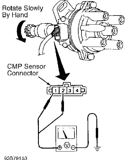
Fig. 1: Distributor Wiring Harness Connector Terminal ID (Altima, NX 1.6L, Sentra 1.6L & 240SX) Courtesy of Nissan Motor Co., U.S.A.
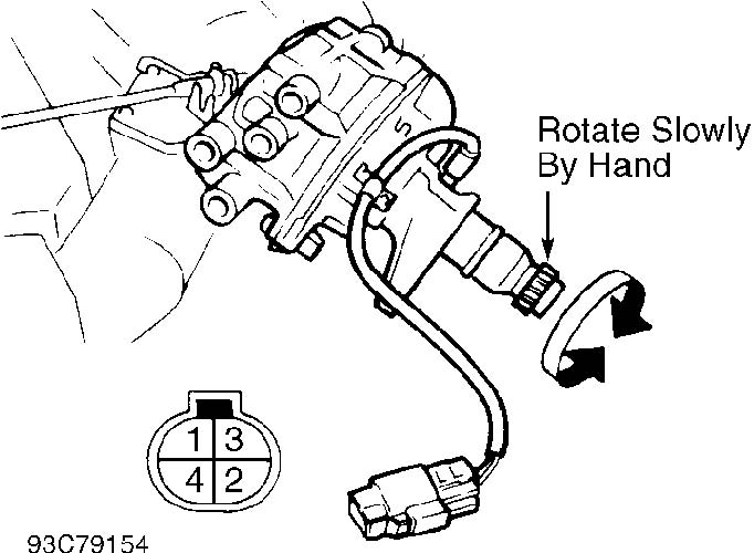
Fig. 2: Distributor Wiring Harness Connector Terminal ID (Maxima, Pathfinder, Pickup 3.0L & Quest) Courtesy of Nissan Motor Co., U.S.A.
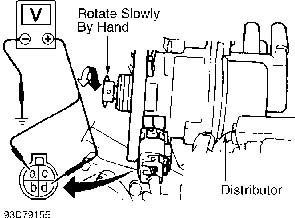
Fig. 3: Distributor Wiring Harness Connector Terminal ID (NX 2.0L, Pickup 2.4L & Sentra 2.0L) Courtesy of Nissan Motor Co., U.S.A.
DISTRIBUTORLESS IGNITION (EI) SYSTEM
To determine cause of no-spark condition, perform following tests in order given. Deviation from this procedure may cause false diagnosis and replacement of non-defective components.
Ignition Coil Power Source & Ground
1) Disconnect 3-pin ignition coil connector. Turn ignition on. Check voltage between ground and terminal "B" of ignition coil connector. See Fig. 4.
2) If battery voltage is not present, go to IGNITION COIL/POWER TRANSISTOR RELAY. If battery voltage exists, turn ignition off. Check continuity between ground and ignition coil connector terminal "A".
3) If continuity does not exist, repair ground circuit between ignition coil connector terminal "A" and ground. Repeat test for remaining coils.
Ignition Coil/Power Transistor Relay
Connect 12-volt power source between relay connector terminals No. 1 and 2. See Fig. 5. Check continuity between terminals No. 3 and 5. If continuity does not exist, replace relay. Disconnect power source. Check continuity between relay connector terminals No. 3 and 5. If continuity exists, replace relay.
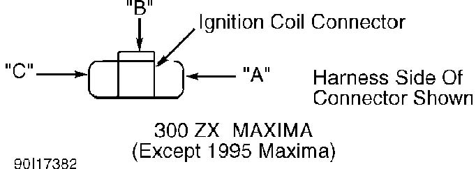
Fig. 4: Ignition Coil Connector Terminal ID (EI) Courtesy of Nissan Motor Co., U.S.A.
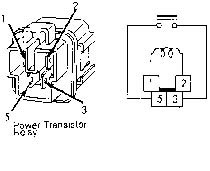
Fig. 5: Ignition Coil/Power Transistor Relay Terminal ID (EI) Courtesy of Nissan Motor Co., U.S.A.
Ignition Coil Resistance Disconnect ignition coil connector. Check primary resistance
between terminals "B" and "C" of ignition coil connector. See Fig. 6. Resistance should be about 0.75 ohm. If resistance is not as specified, replace ignition coil.
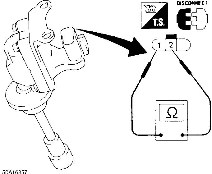
Fig. 6: Identifying Ignition Coil Terminals Courtesy of Nissan Motor Co., U.S.A.
CKP Sensor
1) If a fault is present in CKP sensor, Code 11 may be set in ECM memory. If Code 11 is set, perform appropriate CODE 11 (CKP SENSOR) in G - TESTS W/CODES article.
2) To test CKP sensor, remove distributor. Leave wiring harness connected. Using a voltmeter, connect negative lead to ground and alternately connect positive lead to terminal "A" (120-degree signal) and terminal "B" (1-degree signal). See Fig. 7.
3) Measure voltages while rotating distributor by hand. Voltage should fluctuate 0-5 volts. If either voltage signal does not fluctuate 0-5 volts, check harness for short or open circuit. If no problems are found, replace CKP sensor.
Power Transistor Circuits
Disconnect power transistor unit connector. Check continuity at each power transistor unit terminal. See Fig. 8 or 9. If continuity is not as specified, replace power transistor.
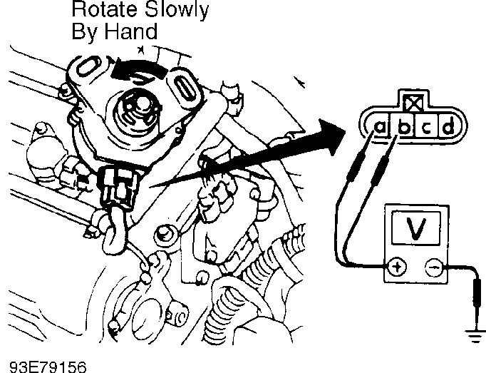
Fig. 7: Crankshaft Sensor Wiring Harness Connector Terminal ID (Maxima VE30DE Shown; 300ZX Is Similar) Courtesy of Nissan Motor Co., U.S.A.
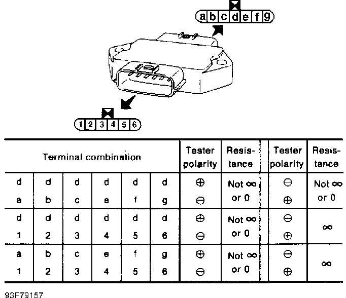
Fig. 8: Power Transistor Terminal & Test Combination ID (Maxima VE30DE) Courtesy of Nissan Motor Co., U.S.A.
Fig. 9: Power Transistor Terminal & Test Combination ID (300ZX) Courtesy of Nissan Motor Co., U.S.A.
IDLE SPEED & IGNITION TIMING
Ensure idle speed and ignition timing are set to specification. Improper setting of ignition timing and idle speed may cause driveability problems and/or false setting of trouble codes. For adjustment procedures, see D - ADJUSTMENTS article.
4-CYLINDER IDLE SPEED & CO LEVEL TABLE
���������������������������������������������������������������������������������������������������������������������������������
| (1) Idle | (2) Idle | (3) Maximum CO | ||||
|---|---|---|---|---|---|---|
| Application | RPM | RPM | Level | |||
| Altima | ......... | (4) 650-750 | . | (4) 600-700 | ......... | 5.0% |
| NX & Sentra | ||||||
1.6L A/T ........... (4) 750-850 . (4) 675-775 ......... 7.0% M/T ............. 600-700 ..... 550-650 ............. 7.0% 2.0L .......... (4) 750-850 . (4) 700-800 ........ 10.0%
Pickup ......... (4) 750-850 . (4) 700-800 ......... 5.0% 240SX .......... (4) 650-750 . (4) 600-700 ......... 7.0%
- (1)
- - With throttle position sensor connected.
- (2)
- - With throttle position sensor disconnected.
- (3)
- - Measured in Self-Diagnostic Mode II.
- (4)
- - Automatic transmission/transaxle in Neutral.
���������������������������������������������������������������������������������������������������������������������������������
V6 IDLE SPEED & CO LEVEL TABLE
���������������������������������������������������������������������������������������������������������������������������������
(1) Idle (2) Idle (3) Maximum CO Application RPM RPM Level
Maxima VE30DE ......... (4) 650-750 . (4) 650-750 ..... 0.2-8.0% VG30E .......... (4) 650-750 ..... (4) 700 ...... 0.2-8.0%
Pathfinder &
Pickup ......... (4) 700-800 ..... (4) 700 ...... 0.2-8.0% Quest ........... (4) 650-750 . (4) 700-800 ..... 0.2-8.0% 300ZX
A/T Non-Turbo ...... (4) 720-820 ..... (4) 720 ...... 0.2-8.0% Turbo .......... (4) 700-800 ..... (4) 700 ...... 0.2-8.0% M/T .............. 650-750 ......... 650 ........ 0.2-8.0%
- (1)
- - With Auxiliary Air Control (AAC) valve connected.
- (2)
- - With Auxiliary Air Control (AAC) valve disconnected.
- (3)
- - Measured in self-diagnostic Mode II.
- (4)
- - Automatic transmission/transaxle in Neutral.
���������������������������������������������������������������������������������������������������������������������������������
4-CYLINDER IGNITION TIMING TABLE (Degrees BTDC @ RPM)
���������������������������������������������������������������������������������������������������������������������������������
Application Man. Trans. (1) Auto. Trans.
Altima & 240SX .... 18-22 @ 700-800 ......... 18-22 @ 700-800
NX & Sentra 1.6L ............. 8-12 @ 600-700 ........... 8-12 @ 800-900 2.0L ............. 13-17 @ 800-900 ......... 13-17 @ 800-900
Pickup ............ 8-12 @ 750-850 ........... 8-12 @ 750-850
(1) - Automatic transmission/transaxle in Neutral.
���������������������������������������������������������������������������������������������������������������������������������
V6 IGNITION TIMING TABLE (Degrees BTDC @ RPM)
���������������������������������������������������������������������������������������������������������������������������������
Application Man. Trans. (1) Auto. Trans.
Maxima, Pathfinder, Pickup & Quest ......... 13-17 @ 700-800 ... 13-17 @ 700-800
300ZX Non-Turbo .............. 13-17 @ 650-750 ... 13-17 @ 720-820 Turbo .................. 13-17 @ 650-750 ... 13-17 @ 700-800
(1) - Automatic transmission/transaxle in Neutral.
���������������������������������������������������������������������������������������������������������������������������������
SUMMARY
If no faults were found while performing BASIC DIAGNOSTIC PROCEDURES proceed to G - TESTS W/CODES article. If no hard codes are found in self-diagnostics, proceed to H - TESTS W/O CODES article for diagnosis by symptom (i.e., ROUGH IDLE, NO START, etc.) or intermittent diagnostic procedures.