
BRAKE SYSTEM
�1993 Nissan Sentra
1993 BRAKES Nissan Disc & Drum
Sentra
DESCRIPTION & OPERATION
All brake systems are operated hydraulically using a tandem master cylinder and vacuum power unit. All models have front disc brakes. Rear brakes are either drum or disc.
BLEEDING BRAKE SYSTEM
BLEEDING PROCEDURES
NOTE: Check fluid level in master cylinder frequently during bleeding procedure.
Bleed brake system in proper sequence. See BRAKELINE BLEEDING SEQUENCE table.
BRAKELINE BLEEDING SEQUENCE TABLE
�������������������������������������������������������������������������������������������������������������
Application Sequence Sentra ............................... LR, RF, RR, LF
�������������������������������������������������������������������������������������������������������������
ADJUSTMENTS
POWER BRAKE UNIT OUTPUT ROD
1) Attach a hand-held vacuum pump to power brake unit supply port. See Fig. 1. Apply 20 in. Hg vacuum to power brake unit. Measure length of output rod extending from power brake unit housing.
2) See POWER BRAKE UNIT OUTPUT ROD LENGTH SPECIFICATIONS table. Adjust output rod length if necessary. If output rod length cannot be adjusted properly, replace power brake unit.
POWER BRAKE UNIT OUTPUT ROD LENGTH SPECS TABLE
�������������������������������������������������������������������������������������������������������������
Application In. (mm)
Sentra 1.6L (8" Booster) .......... .19-.20 (4.8-5.1) Other Models .................... .40-.41 (10.3-10.5)
�������������������������������������������������������������������������������������������������������������
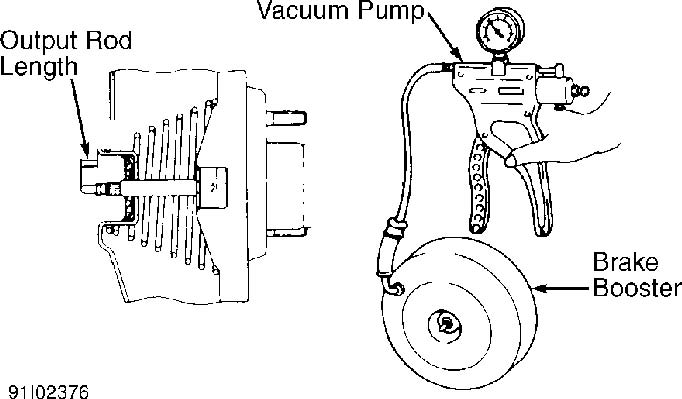
Fig. 1: Measuring Output Rod Length Courtesy of Nissan Motor Co., U.S.A.
BRAKE PEDAL HEIGHT & FREE PLAY
1) Measure pedal height from pressure face of pedal pad to floor pan insulator, without carpet. See BRAKE PEDAL HEIGHT SPECIFICATIONS table.
2) To adjust pedal height, loosen brake booster input rod lock nut, and rotate input rod to attain proper height. Tighten lock nut, and adjust stoplight switch. Ensure pedal free play is .04-.12" (1.0-3.0 mm).
BRAKE PEDAL HEIGHT SPECIFICATIONS TABLE
�������������������������������������������������������������������������������������������������������������
Pedal Height
| Application | In. (mm) | |
|---|---|---|
| Sentra | ||
| A/T | .............................. | 6.2-6.6 (157-167) |
| M/T | .............................. | 5.8-6.2 (148-158) |
�������������������������������������������������������������������������������������������������������������
PARKING BRAKE
1) Remove parking brake lever cover. Raise and support rear of vehicle. Pull up on parking brake lever using force of 44 lbs. (20 kg). Rear wheels should lock at appropriate lever stroke. See PARKING BRAKE LEVER STROKE SPECIFICATIONS table.
2) Adjust parking brake using adjusting nut located beside or below parking brake lever. After releasing lever, ensure rear wheels rotate freely and slack is not present at rear cables.
PARKING BRAKE LEVER STROKE SPECIFICATIONS TABLE
�������������������������������������������������������������������������������������������������������������
| Application | Notches | |
|---|---|---|
| Sentra | ||
| Rear Disc Brake | ................................ | 7-9 |
| Rear Drum Brake | ................................ | 5-7 |
�������������������������������������������������������������������������������������������������������������
REAR BRAKE SHOE CLEARANCE
1) Set shoe adjustment assembly so clearance between brake drum inside diameter and brake shoes outside diameter is as specified. See BRAKE SHOE INSTALLATION CLEARANCE SPECIFICATIONS table.
2) After brake drum installation, depress brake pedal to center shoes. Check pedal travel. Rotate brake drum to verify free movement.
BRAKE SHOE INSTALLATION CLEARANCE SPECIFICATIONS TABLE
�������������������������������������������������������������������������������������������������������������
Application In. (mm)
Sentra .......................... .014-.022 (.36-.56)
�������������������������������������������������������������������������������������������������������������
STOPLIGHT SWITCH & AUTOMATIC SPEED CONTROL DEVICE SWITCH
1) Both switches are located below dash panel, at brake pedal bracket.Adjust brake pedal height. See BRAKE PEDAL HEIGHT & FREE PLAY.
2) Check clearance and position of switches. Clearance between brake pedal stopper rubber and threaded end of switch should be.01-.04" (0.3-1.0 mm). To adjust, loosen lock nut and turn switch body. After adjustment, tighten lock nut.
TESTING
POWER BRAKE UNIT
NOTE: Determine whether source of problem is in power brake unit or check valve. Always inspect check valve.
DO NOT disassemble power brake unit. After air-tight and operational tests, replace complete assembly if problem is determined to be in power brake unit.
Air-Tight Check
1) Start engine, and operate it for 2 minutes. Turn engine off. Depress brake pedal several times. If brake pedal height rises gradually on successive pedal depressions, go to next step. If pedal does not rise on successive pumps, check for air leak.
2) Start engine. Depress brake pedal and turn engine off. Hold brake pedal down for 30 seconds. If brake pedal height does not change, power brake unit is air tight. If pedal height changes, check for air leak.
Operational Check
With engine off, depress brake pedal several times until pedal height no longer changes. Press and hold brake pedal down. Start engine. If pedal goes down slightly, power brake unit is okay. If pedal does not move, check for air leak.
PROPORTIONING VALVE
CAUTION: Check rear brake pressure 2 seconds after front brake
pressure reaches specified value. On vehicles with ABS,
disconnect ABS actuator harness connector.
Using 2 pressure gauges, attach one to front brake bleeder and one to rear brake bleeder. Bleed air from front and rear bleeders. Depress brake pedal until front brake pressure reading is achieved. Check rear brake pressure. See PROPORTIONING VALVE PRESSURE SPECIFICATIONS table. If reading is not as indicated, replace dual proportioning valve (separated type) or master cylinder assembly (built-in type).
PROPORTIONING VALVE PRESSURE SPECIFICATIONS TABLE
�������������������������������������������������������������������������������������������������������������������������������������������
Front Brake Pressure Rear Brake Pressure
��
| Application | psi (kg/cm | ) | psi (kg/cm | ) | |||||
|---|---|---|---|---|---|---|---|---|---|
| Sentra | |||||||||
| With ABS | |||||||||
| Except 2.0L (SE) | .......... | 711 (50) | ............ | 284-341 (20-24) | |||||
| 2.0L (SE) | ................. | 924 (64) | ............ | 498-555 (34-38) | |||||
| Without ABS | |||||||||
| 1.6L | ...................... | 1067 (75) | ........... | 640-697 (45-49) | |||||
| 2.0L (SR) | ................. | 782 (55) | ............ | 356-412 (25-29) | |||||
| 2.0L (SE) | ................. | 995 (70) | ............ | 569-626 (40-44) | |||||
�������������������������������������������������������������������������������������������������������������������������������������������
REMOVAL & INSTALLATION
NOTE: When removing or installing components, refer to appropriate
illustration for exploded view of specific assembly. See
Figs. 2-4.
FRONT BRAKE PADS
Removal
1) Raise and support front of vehicle. Remove wheel assembly. Remove bottom guide pin. Rotate caliper body upward on guide pin.
2) Remove pad retainers, shims and brake pads. Note pad condition and location for proper installation (if reusable). Minimum pad thickness is .08" (2.0 mm) for all models.
Installation
1) Clean piston and area around lock and guide pins. Install inner pad. Seat piston by placing lever through opening in caliper body and pushing piston into bore. Apply brake grease to pad retainer points on caliper assembly. Install outer pad and shims.
2) Install pad retainers. Rotate caliper body down into original position. Install lower lock pin. Tighten bolts to specification, and depress brake pedal several times to seat pads. See TORQUE SPECIFICATIONS table at the end of this article.
FRONT BRAKE CALIPER
Removal
Raise and support front of vehicle. Remove wheel assembly. Disconnect and plug brake line from caliper. Remove caliper mount bolts. Remove caliper assembly.
Installation To install, reverse removal procedure. Tighten caliper mount
bolts to specification. See TORQUE SPECIFICATIONS table at the end of this article. Bleed hydraulic system. See BLEEDING BRAKE SYSTEM.
FRONT BRAKE ROTOR
NOTE: For exploded view of hub assembly, see SUSPENSION - FRONT article in the SUSPENSION section.
Removal & Installation
Raise and support vehicle. Remove wheel assembly. Remove caliper, but DO NOT disconnect brake hose. See FRONT BRAKE CALIPER. Wire caliper aside. Remove rotor from hub. To install, reverse removal procedure.
REAR BRAKE PADS
Removal
1) Raise and support rear of vehicle. Remove rear wheel assembly. Release parking brake. Remove parking brake cable retainer (if equipped). Remove lower pin bolts, lock spring and pad retainer spring (if equipped).
2) Rotate caliper upward. Remove pads and pad shims. Note locations and condition of pads for proper installation (if reusable). Minimum pad thickness is .08" (2.0 mm).
Installation
1) To install, reverse removal procedure. Clean area around pin bolts and piston end. DO NOT damage piston boot. Retract piston into cylinder body by turning it clockwise.
2) On all models, apply silicone brake grease to caliper sliding surfaces and pad contact area on mounting support.
REAR BRAKE CALIPER
Removal
Remove rear wheel assembly. Disconnect hydraulic line from caliper, and plug openings. Disconnect parking brake cable and stay (if equipped). Remove caliper mount bolts, and remove caliper assembly.
Installation
To install, reverse removal procedure. Install and tighten hydraulic line and caliper mount bolts to specification. See TORQUE SPECIFICATIONS table at the end of this article. Bleed hydraulic system. See BLEEDING BRAKE SYSTEM.
REAR BRAKE ROTOR
Removal
Remove caliper. See REAR BRAKE CALIPER. Remove rotor from axle flange. If rotor is difficult to remove, install 2 bolts in rotor and gradually tighten them to remove rotor.
Installation
1) To install, reverse removal procedure.
2) After installation is complete, adjust clearance between pad and rotor by depressing pedal until pedal stroke is constant.
REAR BRAKE DRUM & SHOES
Removal Raise and support vehicle. Remove rear wheel assembly. Remove
drum. Remove brake shoe return springs. Remove adjuster and shoes as an assembly. Separate adjuster and shoes. Remove remaining components, and mark for installation reference.
Installation
1) To install, reverse removal procedure. Apply Lubriplate to backing plate bosses, adjuster assembly threads and parking brake lever pin.
2) Before installing drum, adjust brake shoe clearance. See REAR BRAKE SHOE CLEARANCE under ADJUSTMENTS. After installation is complete, depress brake pedal to center shoes, and check pedal travel. Rotate brake drum to ensure free movement.
MASTER CYLINDER
Removal
Disconnect electrical wiring at cylinder reservoir. Disconnect and plug hydraulic lines at master cylinder. Drain fluid from reservoir. Remove cylinder mounting nuts, and remove master cylinder.
Installation
To install, reverse removal procedure. Bleed hydraulic system. See BLEEDING BRAKE SYSTEM. Check pedal height. See BRAKE PEDAL HEIGHT & FREE PLAY under ADJUSTMENTS.
POWER BRAKE UNIT
Removal
Remove master cylinder. See MASTER CYLINDER. Disconnect power unit push rod from brake pedal by removing clevis pin. Disconnect vacuum line from power brake unit. Remove power brake unit-to-firewall nuts. Remove power brake unit.
Installation
To install, reverse removal procedure. Before installing master cylinder, adjust booster output push rod. See POWER BRAKE UNIT OUTPUT ROD under ADJUSTMENTS.
POWER BRAKE UNIT CHECK VALVE
Removal & Installation
1) Check valve is located in vacuum line between intake manifold and power brake unit. To remove, disconnect retaining clip from firewall (if equipped). Remove hose clamps, separate hoses from valve, and remove check valve.
2) Inspect check valve to ensure air flows in direction of intake manifold only. If air flows both ways or does not flow at all, replace check valve. To install, reverse removal procedure.
OVERHAUL
NOTE: Overhaul procedures are not available from manufacturer.
Refer to appropriate illustration for exploded view of
specific assembly. See Figs. 2-4.
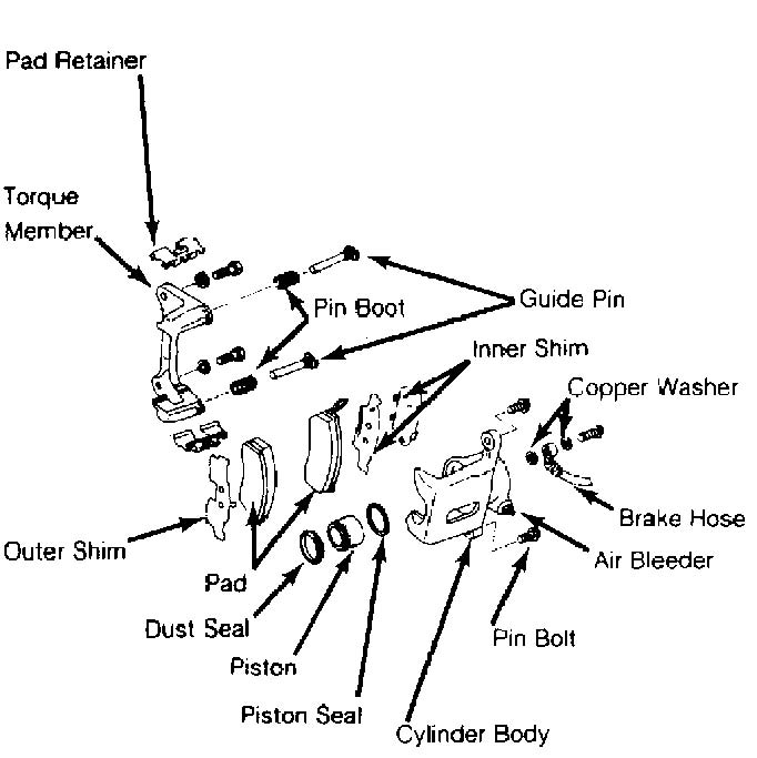
Fig. 2: Exploded View Of Front Brake Caliper (Typical) Courtesy of Nissan Motor Co., U.S.A.
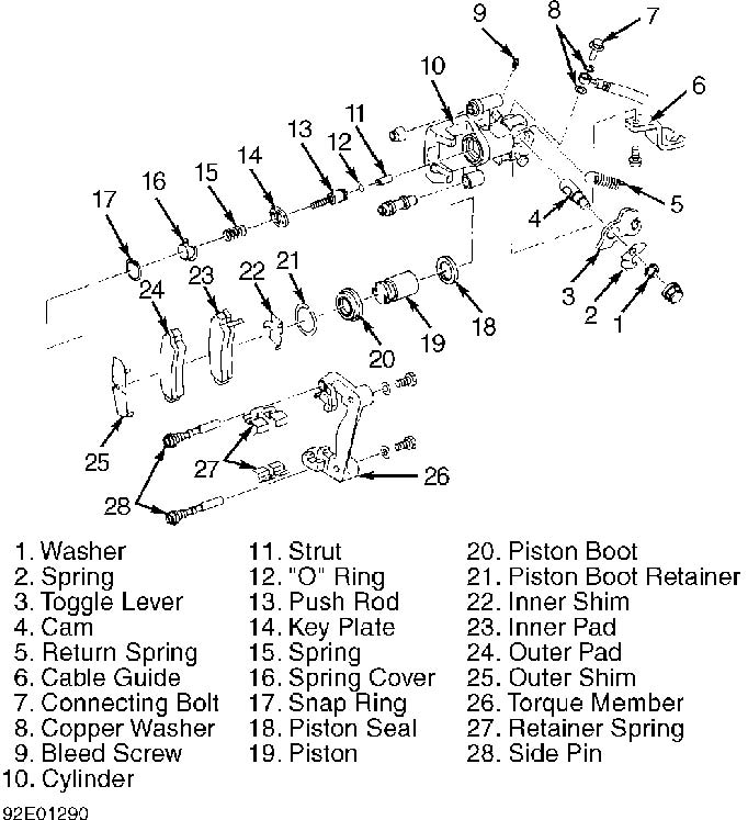
Fig. 3: Exploded View Of Rear Disc Brake Caliper Courtesy of Nissan Motor Co., U.S.A.
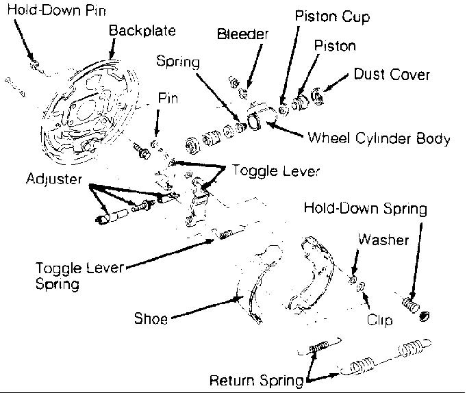
Fig. 4: Exploded View Of Rear Drum Brakes Courtesy of Nissan Motor Co., U.S.A.
TORQUE SPECIFICATIONS
TORQUE SPECIFICATIONS TABLE
�������������������������������������������������������������������������������������������������������������������������������������������
Application Ft. Lbs. (N.m)
Backing Plate Mount Bolt/Nut (Rear) ................... 28-38 (38-52) Booster Input Rod Lock Nut ........................... 12-16 (16-22) Brake Line Bolt ...................................... 12-14 (16-19) Brake Line Flare Nut ................................. 11-13 (15-18) Brake Pedal Fulcrum Shaft Nut ........................ 12-16 (16-22) Caliper-To-Torque Member Bolt
1.6L ................................................ 16-23 (22-31)
2.0L ................................................ 23-30 (31-41) Torque Member-To-Mount Bolt
Front ................................................ 40-47 (54-64)
Rear ................................................ 28-38 (38-52) Wheel Lug Nuts ....................................... 72-87 (98-118)
INCH Lbs. (N.m)
Master Cylinder Mount Nut ............................. 72-96 (8-11) Power Brake Unit-To-Firewall Nut ................... 108-144 (12-16)
�������������������������������������������������������������������������������������������������������������������������������������������
DISC BRAKE SPECIFICATIONS
DISC BRAKE SPECIFICATIONS TABLE
�������������������������������������������������������������������������������������������������������������������������������������������
| Application | In. (mm) |
| Disc Diameter Front 1.6L ................................................ | 9.45 (240.0) |
2.0L SE Model ........................................... 10.12 (257.0) SR Model ............................................ 9.84 (249.9)
Rear ................................................. 9.21 (233.9) Disc Thickness (Std.)
Front 1.6L .................................................. .71 (18.0) 2.0L SE Model ............................................. 1.02 (25.9) SR Model .............................................. .71 (18.0)
Rear .................................................... .28 (7.1) Lateral Runout ........................................... .003 (.08) Master Cylinder Bore Diameter
1.6L With ABS ............................................ .875 (22.22) Without ABS Standard ............................................ .750 (19.05) GXE & XE Models ..................................... .813 (20.64)
2.0L ................................................. .875 (22.22) Minimum Disc Thickness Front
Without ABS 1.6L ................................................. .63 (16.0) 2.0L
SE Model (1) ........................................ .63 (16.0) SR Model ............................................ .63 (16.0)
With ABS 1.6L ................................................. .63 (16.0) 2.0L
SE Model ........................................... .945 (24.0) SR Model ............................................ .63 (16.0) Rear .................................................... .24 (6.1)
(1) - Sports package is .945 inch (.240 mm)
�������������������������������������������������������������������������������������������������������������������������������������������
DRUM BRAKE SPECIFICATIONS
DRUM BRAKE SPECIFICATIONS TABLE
�������������������������������������������������������������������������������������������������������������������������������������������
Application In. (mm)
Drum Diameter .......................................... 7.09 (180.1) Master Cylinder Bore Diameter
Standard ............................................. .750 (19.05)
GXE & XE Models ...................................... .813 (20.64) Maximum Out-Of-Round ................................... .0012 (.030) Maximum Refinish Diameter .............................. 7.13 (181.1) Runout ................................................... .002 (.05) Wheel Cylinder Bore Diameter ........................... .625 (15.88)
�������������������������������������������������������������������������������������������������������������������������������������������