
CLUTCH
�1993 Nissan Sentra
1993 CLUTCH Mechanical
Nissan: NX, Sentra
DESCRIPTION
Clutch assembly is a single disc type with a diaphragm spring pressure plate. Use a mechanical control system consisting of clutch cable, release lever and release bearing.
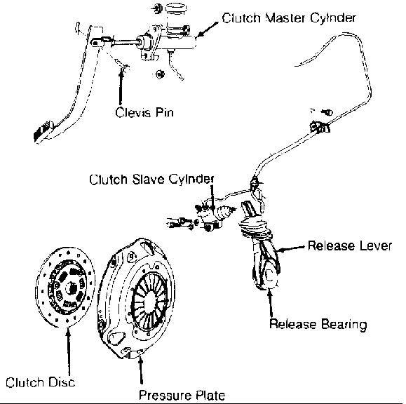
Fig. 1: Exploded View Of Typical Hydraulic Clutch System Courtesy Of Nissan Motor Co., U.S.A.
ADJUSTMENTS
NOTE: Adjust clutch pedal height before adjusting free play.
CLUTCH INTERLOCK SWITCH
Clutch interlock switch is located on clutch pedal bracket. With clutch pedal fully depressed, adjust clearance between rubber stopper and threaded end of interlock switch. Clearance should be . 004-.039" (0.10-1.00 mm).
CLUTCH PEDAL HEIGHT
Clutch pedal height is adjusted by adjusting clutch pedal stopper or clutch switch, located below pedal hinge. See Fig. 2. Loosen lock nut. Rotate clutch pedal stopper or clutch switch until pedal height is as specified in CLUTCH PEDAL HEIGHT SPECIFICATIONS table. Tighten lock nut.
CLUTCH PEDAL HEIGHT SPECIFICATIONS TABLE
�����������������������������������������������������������������������������������������������������������������������
Application In. (mm)
NX & Sentra .......................... 5.91-6.30 (150-160)
�����������������������������������������������������������������������������������������������������������������������
CLUTCH PEDAL FREE PLAY
Mechanical Clutch (NX & Sentra)
1) Adjust free play at release lever end of clutch cable. See Fig. 2. Loosen lock nut. Apply hand pressure to release lever in direction of clutch disengagement to remove free play. Tighten adjusting nut.
2) Back off adjusting nut 2.5-3.5 turns. Free play at release lever clevis pin should be .10-.14" (2.5-3.5 mm). Free play at clutch pedal pad should be .43-.59" (10.9-15.0 mm).
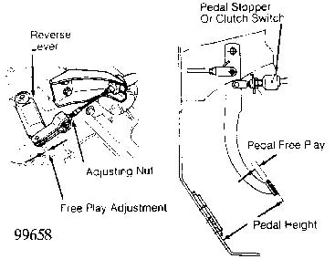
Fig. 2: Adjusting Clutch Pedal (Mechanical Clutch Shown; Typical) Courtesy of Nissan Motor Co., U.S.A.
REMOVAL & INSTALLATION
CAUTION: When battery is disconnected, vehicle computer and memory
systems may lose memory data. Driveability problems may
exist until computer systems have completed a relearn cycle.
CLUTCH ASSEMBLY
Removal
1) Remove battery and battery holder plate. Remove air cleaner and airflow meter. Disconnect clutch cable or remove clutch slave cylinder. Disconnect speedometer cable and electrical connectors.
2) Remove starter. Disconnect shift control rod, and shift support rod from transaxle. Drain transaxle gear oil. Remove front wheels. On NX and Sentra, remove front exhaust tube. On all models, remove drive axles. See the AXLE SHAFTS - FRONT article in the DRIVE AXLES section.
3) Support rear of engine using jack. Remove left and rear engine mounts. Support transaxle using jack. Remove transaxle-toengine bolts. Remove transaxle. Loosen pressure plate bolts in crisscross pattern. Remove disc and pressure plate.
NOTE: All components except clutch disc and release bearing can be cleaned in solvent.
Inspection
1) Check clutch disc for wear. Minimum wear limit of lining above rivet heads is .012" (.3 mm). Check disc runout by mounting disc onto input shaft. Mount dial indicator to transaxle case. Set indicator plunger against face of disc at specified distance from hub center. See CLUTCH DISC MAXIMUM RUNOUT SPECIFICATIONS table.
2) Replace clutch disc if runout exceeds specification. Measure backlash (spline looseness) at outer edge of disc. SRefer to the CLUTCH DISC MAXIMUM BACKLASH SPECIFICATIONS table. Replace clutch disc if backlash exceeds specification.
3) Check disc hub fit on input shaft splines. Disc should slide smoothly. Check end surface of pressure plate diaphragm springs for wear. Inspect thrust springs by shaking pressure plate assembly. Tap lightly on rivets. Replace assembly if noise is heard.
4) Check difference in height between diaphragm spring fingers. Adjust diaphragm fingers if height differential exceeds specification.
5) Inspect flywheel and pressure plate for scoring, grooves and warpage. Dress light roughness on pressure plate and flywheel using fine emery cloth. Machine flywheel surface (if necessary). If surfaces are deeply scored, replace flywheel or pressure plate.
CLUTCH DISC MAXIMUM RUNOUT SPECIFICATIONS TABLE (1)
���������������������������������������������������������������������������������������������������������������������
Application Radius: In. (mm) Runout: In. (mm)
1.6L ............... 3.54 (90) ............. .039 (.99) 2.0L ............... 4.04 (103) ............. .039 (.99)
(1) - Distance from hub center where runout is to be measured.
�����������������������������������������������������������������������������������������������������������������������
CLUTCH DISC MAXIMUM BACKLASH SPECIFICATIONS TABLE
�����������������������������������������������������������������������������������������������������������������������
Application In. (mm)
1.6L .......................................... .031 (.79) 2.0L .......................................... .035 (.89)
�����������������������������������������������������������������������������������������������������������������������
Installation
1) Lubricate input shaft splines and contact surfaces of release fork and bearing. Ensure disc slides easily on splines. Remove excess grease from components. Install clutch assembly, ensuring clutch is aligned with appropriate-sized clutch aligner.
2) Tighten bolts evenly in a diagonal pattern to specification. See TORQUE SPECIFICATIONS table. Install transaxle in reverse order of removal. Fill the transaxle with gear oil. Adjust clutch pedal height and free play. Refer to CLUTCH PEDAL HEIGHT and CLUTCH PEDAL FREE PLAY under ADJUSTMENTS.
CLUTCH CABLE (NX & SENTRA)
NOTE: After installing clutch cable, adjust clutch pedal free play. See CLUTCH PEDAL FREE PLAY under ADJUSTMENTS.
Removal & Installation
Disconnect clutch cable at transaxle and clutch pedal. Remove clutch cable. To install, reverse removal procedure.
CLUTCH RELEASE FORK & BEARING
Removal
1) Remove transaxle. See CLUTCH ASSEMBLY under REMOVAL & INSTALLATION. Disconnect retainer springs from release bearing and note locations for proper reinstallation. Remove bearing.
2) Align release fork retaining pins with cavities in transaxle. Using a pin punch, drive out retaining pins that hold shaft and release fork together. Remove shaft, spring and release fork.
Inspection
Check contact areas of release bearing and fork for excessive wear. Check release bearing for noise and roughness. Inspect return spring and release bearing spring for wear. Replace components as necessary.
Installation
1) Using a lithium-based grease, lubricate inner groove of release bearing. Lubricate contact surfaces of release fork, bearing, control shaft and housing. DO NOT use excessive lubricant on clutch sliding components.
2) To install, reverse removal procedure. On NX and Sentra, align holes in shaft and release fork. Drive in retaining pins. On all models, install release bearing retainer springs on bearing. When installing release bearing, verify bearing springs are secured on fork.
TORQUE SPECIFICATIONS
TORQUE SPECIFICATIONS TABLE
�����������������������������������������������������������������������������������������������������������������������
Application Ft. Lbs. (N.m)
Clutch Pedal Stopper Lock Nut .............. 12-16 (16-22) Flywheel-To-Crankshaft Bolt ................ 61-69 (83-94) Pressure Plate-To-Flywheel Bolt (1) ........ 16-22 (22-30) Slave Cylinder Mounting Bolt ............... 22-30 (30-41) Starter Motor Bolt
1.6L ..................................... 22-30 (30-41)
2.0L ..................................... 30-38 (41-52)
Transaxle-To-Engine Bolt 1.6L Small Diameter ......................... 12-15 (16-20) Large Diameter ......................... 22-30 (30-41) 2.0L Small Diameter ......................... 22-30 (30-41) Large Diameter ......................... 51-59 (69-80)
INCH Lbs. (N.m)
Clutch Interlock Switch Lock Nut ......... 106-133 (12-15) Cruise Control Switch Lock Nut ........... 106-133 (12-15) Master Cylinder Mounting Nut ................ 71-97 (8-11) Slave Cylinder Bleeder Screw ................ 53-89 (6-10)
(1) - Tighten bolts evenly in a diagonal pattern.
�����������������������������������������������������������������������������������������������������������������������