
CRUISE CONTROL SYSTEM
�1993 Nissan Sentra
1993 ACCESSORIES/SAFETY EQUIPMENT Nissan Cruise Control Systems
Sentra
DESCRIPTION & OPERATION
NOTE: For system component locations, see SYSTEM COMPONENT LOCATIONS table under DESCRIPTION & OPERATION.
ACTUATOR
Actuator pump contains a vacuum pump motor and control valve assembly. Control valve assembly regulates vacuum supply to diaphragm based on signals received from cruise control module.
BRAKE CANCEL, BRAKELIGHT & CLUTCH SWITCHES
NOTE: DO NOT confuse brake cancel switch (activated by braking) with CANCEL switch on steering wheel. See STEERING SWITCH.
These switches disengage system. Brake cancel switch and brakelight switch are separate switches. When brake pedal is pressed:
- *
- Brakelight switch allows current flow to control module.
- *
- Brake cancel switch interrupts current flow to control module.
If either condition occurs, control module disengages the system. When clutch pedal is pressed, clutch switch interrupts current flow to control module. This disengages system.
CRUISE CONTROL MODULE
Based on inputs received from various sensors, cruise control module sends signals to actuator control valve assembly to maintain vehicle speed.
INHIBITOR RELAY (A/T)
When transmission is in Park or Neutral, inhibitor relay interrupts current flow to cruise control module, disengaging system.
MAIN SWITCH
Switch is mounted on instrument panel and supplies power for system.
STEERING SWITCH
Steering switch is a system control switch, mounted on steering wheel. Steering switch has 3 different switches, controlling different functions of system. Steering switch contains RESUME/ACCEL, CANCEL and SET/COAST switches.
SYSTEM COMPONENT LOCATIONS
SYSTEM COMPONENT LOCATIONS
�����������������������������������������������������������������������������������������������������������������������
| Application | Location | |
| Cruise Control Module | ............ | Behind Dash, To Left Of |
| Steering Column |
Cruise Control Relay (1) ...... Near Cruise Control Module Vehicle Speed Sensor ............. Mounted On Transmission
(1) - Relay is Blue.
�����������������������������������������������������������������������������������������������������������������������
TROUBLE SHOOTING
NOTE: For system component locations, see SYSTEM COMPONENT LOCATIONS under DESCRIPTION & OPERATION.
SYSTEM WILL NOT ENGAGE
1) Turn ignition on. Turn cruise control main switch to ON position. If indicator light illuminates, go to next step. If indicator light does not illuminate, check for blown fuse, open in power supply circuit to main switch or faulty cruise control main switch. If these components are okay, perform CRUISE CONTROL RELAY test under TESTING.
2) Perform POWER SUPPLY CIRCUIT test under TESTING. If power supply circuit is okay, perform CUT-OFF CIRCUIT test under TESTING. If cut-off circuit is okay, perform SET/COAST SWITCH CIRCUIT test under TESTING.
3) If SET/COAST switch circuit is okay, perform SPEED SENSOR CIRCUIT test under TESTING. If speed sensor circuit is okay, perform ACTUATOR test under TESTING. If actuator is okay, measure resistance between cruise control module connector terminal No. 8 and terminals No. 9, 10 and 14. See Fig. 2 and 3.
4) If resistance is not about 8-45 ohms when measuring between terminals No. 8 and 9, and about 65 ohms when measuring between terminal No. 8 and terminals No. 10 and 14, repair harness. If resistance is as specified, replace cruise control module.
SYSTEM WILL NOT DISENGAGE
NOTE: Use the following procedure if system will not disengage
when pressing brake or clutch pedal, or when shifting
automatic transmission into Park or Neutral. If system will
not disengage when activating CANCEL switch, see CANCEL
SWITCH FUNCTION INOPERATIVE.
1) If system will not disengage when the brake or clutch (M/T) pedals are pressed or when transmission is placed in Park or Neutral, perform CUT-OFF CIRCUIT test under TESTING.
2) If cut-off circuit does not test okay, check brake cancel switch, clutch switch (M/T), inhibitor relay (A/T) and inhibitor switch (A/T). If cut-off circuit is okay, perform ACTUATOR test under TESTING. If actuator is okay, replace cruise control module.
ENGINE SURGES
Check for loose, cracked or disconnected vacuum hoses. Ensure actuator cable moves smoothly. Repair or replace actuator cable if cable does not move smoothly. If actuator cable moves smoothly, perform ACTUATOR test under TESTING. If actuator is okay, replace cruise control module.
CANCEL SWITCH FUNCTION INOPERATIVE
Perform CANCEL SWITCH CIRCUIT (STEERING WHEEL) test under TESTING. If CANCEL switch circuit is okay, replace cruise control module.
RESUME FUNCTION INOPERATIVE
Perform RESUME SWITCH CIRCUIT test under TESTING. If RESUME/ACCEL switch circuit is okay, replace cruise control module.
ACCEL FUNCTION INOPERATIVE
Perform RESUME SWITCH CIRCUIT test under TESTING. If RESUME switch circuit tests okay, replace cruise control module.
DIFFERENCE BETWEEN SET SPEED & ACTUAL SPEED
Check actuator cable for smoothness of operation. Replace actuator cable if cable does not move smoothly. If actuator cable moves smoothly, check for loose, cracked or disconnected vacuum hoses. If vacuum hoses are okay, perform ACTUATOR test under TESTING. If actuator is okay, replace cruise control module.
OVERDRIVE CANCEL FUNCTION INOPERATIVE
NOTE: Symptoms of inoperative overdrive cancel function include:
- *
- When cruise control is set and transmission is in overdrive, overdrive is canceled and it is not possible to shift back into overdrive.
- *
- Overdrive will not be canceled, even if actual speed is 4 MPH lower than set speed (set speed cannot be maintained).
- *
- Overdrive will not be canceled, even if accelerator switch is on.
Perform OVERDRIVE CANCEL CIRCUIT (A/T) test under TESTING. If overdrive cancel circuit is okay, replace cruise control module.
EXCESSIVELY DELAYED ENGAGEMENT
NOTE: Some delay of engagement is normal.
Check adjustment of actuator cable. See ACTUATOR CABLE under ADJUSTMENTS. Ensure actuator cable moves smoothly. Replace actuator cable if cable does not move smoothly. Check for loose, cracked or disconnected vacuum hoses. If vacuum hoses are okay, perform ACTUATOR test under TESTING. If actuator is okay, replace cruise control module.
CRUISE INDICATOR LIGHT BLINKS
1) If indicator light does not blink when cruise control main switch is turned to ON position again, go to step 3). If indicator light blinks when brake pedal is pressed slowly, adjust brake cancel and brakelight switches. See BRAKE CANCEL, BRAKELIGHT & CLUTCH SWITCHES under ADJUSTMENTS.
2) If indicator light does not blink when brake pedal is pressed slowly, check steering switch. If steering switch is okay, replace cruise control module.
3) Perform ACTUATOR test under TESTING. If actuator is okay, measure voltage between cruise control module connector terminals No.
3 and 8. If voltage is present, check wiring harness. If no voltage is present, disconnect cruise control module connector.
4) Measure resistance between cruise control module connector terminal No. 8 and terminals No. 9, 10 and 14. See Fig. 2 and 3. If resistance is not about 8-45 ohms between terminals No. 8 and 9, and about 65 ohms between terminal No. 8 and terminals No. 10 and 14, repair harness. If resistance is as specified, replace cruise control module.
ADJUSTMENTS
ACTUATOR CABLE
NOTE: Before adjusting actuator (cruise control) cable, ensure
throttle cable is properly adjusted. DO NOT twist or
overtighten cable wire during adjustment procedure.
Loosen actuator cable adjusting nuts. Without pressing accelerator pedal, adjust cable until there is no free play. Back off cable adjusting nut 1/2 - 1 turn to allow slight free play in cable. Tighten cable adjusting nuts.
BRAKE CANCEL, BRAKELIGHT & CLUTCH SWITCHES
Loosen lock nut. Turn adjusting nut until clearance between tip of switch and pedal is .012-.040" (.30-1.0 mm).
TESTING
NOTE: For system component locations, see SYSTEM COMPONENT LOCATIONS under DESCRIPTION & OPERATION.
ACCEL SWITCH CIRCUIT
See RESUME SWITCH CIRCUIT test.
ACTUATOR
1) Turn ignition off. Disconnect actuator pump connector. Connect battery positive lead to actuator pump connector terminal No. 1 and negative lead to terminal No. 4. See Fig. 1.
2) Replace actuator pump if it does not operate. If actuator pump operates, connect battery positive lead to terminal No. 1 and negative lead to terminals No. 2, 3 and 4 (simultaneously).
3) If actuator wire moves, go to next step. If actuator wire does not move, check for vacuum at actuator hose connection. If no vacuum is present, replace actuator pump. If vacuum is present, replace actuator.
4) With battery leads connected to terminals as in step 2), disconnect negative lead from terminal No. 4. If actuator wire returns to original position 50-60 seconds after disconnecting negative lead from terminal No. 4, go to next step. If actuator wire does not return as specified, replace actuator pump.
5) Disconnect negative lead from terminal No. 1. If actuator wire does not immediately return to original position, replace actuator pump. If actuator wire immediately returns to original position, actuator and actuator pump are okay.
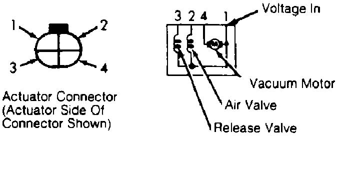
Fig. 1: Actuator Connector Terminal ID Courtesy of Nissan Motor Co., U.S.A.
CANCEL SWITCH CIRCUIT (STEERING WHEEL)
1) Turn ignition on. Press and hold CANCEL switch. Measure voltage between cruise control module connector terminals No. 1 and 3, and terminals No. 2 and 3. See Fig. 2 and 3.
2) If battery voltage is present in each case, CANCEL switch circuit is okay. If battery voltage is not present in each case, check CANCEL switch wiring circuit. If CANCEL switch wiring circuit is okay, replace steering switch assembly.
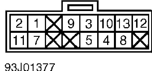
Fig. 2: Cruise Control Module Connector Terminal ID (16-Cavity) Courtesy of Nissan Motor Co., U.S.A.
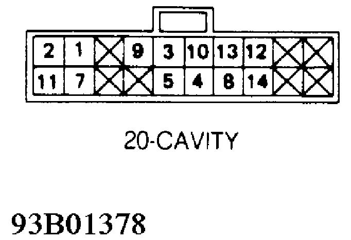
Fig. 3: Cruise Control Module Connector Terminal ID (20-Cavity) Courtesy of Nissan Motor Co., U.S.A.
CRUISE CONTROL RELAY
1) Remove relay. Ensure continuity exists across terminals No. 1 and 2, and no continuity exists across terminals No. 3 and 5. If continuity is not as specified, replace relay.
2) Connect 12-volt source across terminals No. 1 and 2. See Fig. 4. With relay energized, check continuity between terminals No. 3 and 5. If there is no continuity, replace relay. If there is continuity, relay is okay.
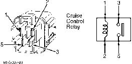
Fig. 4: Cruise Control Relay Connector Terminal ID Courtesy of Nissan Motor Co., U.S.A.
CUT-OFF CIRCUIT
NOTE: This test also includes testing brake or stoplight circuit.
Turn ignition on. Turn cruise control main switch on. Connect voltmeter between cruise control module connector terminals No. 3 and
5. See Fig. 2 and 3. If battery voltage is not present with brake pedal pressed, clutch pedal pressed (M/T) or transmission in Park or Neutral (A/T), check brake and clutch cancel switches and adjust or replace as necessary. See BRAKE CANCEL, BRAKELIGHT & CLUTCH SWITCHES under ADJUSTMENTS. Check inhibitor relay and switch.
GROUND CIRCUIT
Using an ohmmeter, check continuity between ground and cruise control module connector terminal No. 3. See Fig. 2 and 3. If there is no continuity, repair circuit between cruise control module connector and ground.
OVERDRIVE CANCEL CIRCUIT (A/T)
Turn ignition on. Turn cruise control main switch to ON position. Place transmission overdrive switch in ON position. Measure voltage between cruise control module connector terminals No. 3 and
12. See Fig. 2 and 3. If battery voltage is NOT present, check overdrive cancel wiring circuit.
POWER SUPPLY CIRCUIT
1) Release all pressure from brake and clutch pedals. Turn ignition on. Turn cruise control main switch to ON position. Place automatic transmission in Drive.
2) Measure voltage between cruise control module connector terminals No. 3 and 4. See Fig. 2 and 3. If battery voltage is present, power supply circuit is okay. If battery voltage is not present, check power supply circuit.
RESUME SWITCH CIRCUIT
1) Turn ignition on. Press and hold RESUME/ACCEL switch. Measure voltage between cruise control module connector terminals No. 1 and 3. See Fig. 2 and 3.
2) If battery voltage is NOT present, check RESUME/ACCEL switch wiring circuit. If RESUME/ACCEL switch wiring circuit is okay, replace RESUME/ACCEL switch.
SET/COAST SWITCH CIRCUIT
1) Turn ignition off. Press and hold SET/COAST switch. Measure voltage between cruise control module connector terminals No. 2 and 3. See Fig. 2 and 3.
2) If battery voltage is NOT present, check SET/COAST switch wiring circuit. If SET/COAST switch wiring circuit is okay, replace SET/COAST switch.
SPEED SENSOR CIRCUIT
1) Raise and support rear of vehicle. Turn ignition on. Connect voltmeter between cruise control module connector terminals No. 3 and 7. See Fig. 4.
2) While slowly turning rear wheel, check for voltmeter needle deflection. If needle deflects, speed sensor and circuit are okay. If needle does not deflect, check speed sensor. If speed sensor is okay, check speed sensor wiring circuit.
SPEED SENSOR
1) Disconnect speed sensor connector. Remove sensor from transmission. While turning sensor gear counterclockwise quickly by hand, measure AC voltage across sensor connector terminals. If about . 5 volt AC is not present, replace sensor.
REMOVAL & INSTALLATION
ACTUATOR
Turn ignition off. Disconnect actuator harness connector, vacuum hose and cable from actuator. Remove actuator attaching bolt. To install, reverse removal procedure.
ACTUATOR CABLE
Disconnect cable from actuator. Remove screw attaching cable bracket. Remove rubber boots. Loosen lock nuts and remove cable from torsion shaft. To install cable, reverse removal procedure and adjust.
BRAKELIGHT, BRAKE CANCEL & CLUTCH SWITCHES
Disconnect negative battery cable. Remove instrument panel lower left cover. Disconnect wiring harness from switch. Loosen lock nut and remove switch. To install, reverse removal procedure. Adjust switch. See ADJUSTMENTS.
CRUISE CONTROL MODULE
For cruise control module location, see SYSTEM COMPONENT LOCATIONS under DESCRIPTION & OPERATION. Turn ignition off. Disconnect negative battery cable. Remove cruise control module mounting hardware. Remove cruise control module and disconnect harness connector. To install, reverse removal procedure.
MAIN SWITCH
Disconnect negative battery cable. Push switch out from behind instrument panel or from below console. Disconnect harness connector from main switch. To install, reverse removal procedure.
WIRING DIAGRAMS
Proceed to chassis WIRING DIAGRAMS in WIRING DIAGRAMS section.