ENGINE COOLING FAN
�1993 Nissan Sentra
1993 ENGINE COOLING Nissan Specifications & Electric Cooling Fans
Sentra
SPECIFICATIONS
BELT ADJUSTMENT
BELT TENSION ADJUSTMENT TABLE
�������������������������������������������������������������������������������������������������������������������������������������������
Application (1) Deflection - In. (mm)
Alternator ................................................ 5/16 (8) A/C Compressor ............................................ 9/32 (7) Power Steering Pump ....................................... 3/16 (5)
(1) - Deflection is with pressure of 22 lbs. (10 kg) applied midway on the longest run of NEW belt.
�������������������������������������������������������������������������������������������������������������������������������������������
COOLING SYSTEM SPECIFICATIONS
COOLING SYSTEM SPECIFICATIONS TABLE
�������������������������������������������������������������������������������������������������������������������������������������������
| Application | Specification | |
|---|---|---|
| Coolant Replacement Interval | .......................... | 30,000 Miles |
| 24 Months | ||
| Coolant Capacity (1) | ||
1.6L Automatic Transmission ........................... 5.6 Qts. (5.3L) Manual Transmission .............................. 5.4 Qts. (5.1L)
2.0L Automatic Transmission ........................... 6.1 Qts. (5.8L) Manual Transmission .............................. 5.9 Qts. (5.6L)
Pressure Cap ............................................. 11-14 psi
��
Thermostat Opening Temperature ........................ 170 F (77 C)
(1) - Including heater core.
�������������������������������������������������������������������������������������������������������������������������������������������
COOLING SYSTEM BLEEDING
NOTE: On the 1.6L use 2 air relief plugs. On the 2.0L use an air bleeder cap on heater hose pipe in addition to air relief plug(s).
Before filling cooling system, ensure heater valve is open to allow coolant flow through heater core. See OPENING HEATER VALVE table. When filling cooling system, ensure air relief plug is loose to allow trapped air to exit system. See Fig. 1, 2, 3 and 4. Tighten air relief plug after filling cooling system.
OPENING HEATER VALVE TABLE
�������������������������������������������������������������������������������������������������������������������������������������������
Application Procedure
Manual A/C ................................ Move Temperature Control
Lever To Full HOT Position.
�������������������������������������������������������������������������������������������������������������������������������������������

Fig. 1: Locating Air Relief Plug "A" (1.6L) Courtesy of Nissan Motor Co., U.S.A.

Fig. 2: Locating Air Relief Plug "B" (1.6L) Courtesy of Nissan Motor Co., U.S.A.

Fig. 3: Locating Air Bleeder Cap (2.0L) Courtesy of Nissan Motor Co., U.S.A.

Fig. 4: Locating Air Relief Plug (2.0L) Courtesy of Nissan Motor Co., U.S.A.
ELECTRIC COOLING FAN
TROUBLE SHOOTING & TESTING
NOTE: ECM refers to ECCS control unit. ECM controls cooling fan
operation based on inputs from coolant temperature sensor
and A/C switch.
Radiator (Cooling) Fan Control Test (1.6L A/T With A/C)
1) Start engine and warm to operating temperature. Set temperature lever to full cold. Turn A/C switch on. Turn fan switch on. Run engine at idle with A/C on for several minutes. Ensure radiator fan operates at low speed. If radiator fan does not operate at low speed, go to RADIATOR (COOLING) FAN LOW SPEED CONTROL TEST (1. 6L A/T). If radiator fan operates at low speed, go to next step.
2) Turn A/C and fan switches off. Turn ignition off. Disconnect radiator fan relay No. 1. Start engine and idle until
��
engine temperature is greater than 221 F (105 C). Ensure radiator fan operates at high speed. If radiator fan does not operate at high speed, see RADIATOR (COOLING) FAN HIGH SPEED CONTROL TEST (1.6L A/T). If radiator fan operates at high speed, system is functioning properly.
Radiator (Cooling) Fan Control Test (1.6L A/T Without A/C)
1) Start engine and warm to operating temperature. Ensure radiator fan operates at low speed during warm-up. If radiator fan does not operate at low speed, go to RADIATOR (COOLING) FAN LOW SPEED CONTROL TEST (1.6L A/T). If radiator fan operates at low speed, go to next step.
2) Turn ignition off. Disconnect radiator fan relay No. 1.� Start engine and idle until engine temperature is greater than 221 F (105 � C). Ensure radiator fan operates at high speed. If radiator fan does not operate at high speed, see RADIATOR (COOLING) FAN HIGH SPEED CONTROL TEST (1.6L A/T). If radiator fan operates at high speed, system is functioning properly.
Radiator (Cooling) Fan Low Speed Control Test (1.6L A/T)
1) Turn ignition off. Disconnect radiator fan relay No. 1. See Fig. 10, 11 and 12. Turn ignition on. Measure voltage between ground and radiator fan relay No. 2 harness connector terminals No. 2 (White/Green wire) and No. 5 (Black/White wire). See Fig. 5 and 6. Battery voltage should be present. If battery voltage is present, go to step 3). If battery voltage is not present, go to next step.
2) Check 10-amp fuse located in fuse box under left instrument panel. Replace fuse as necessary. Check 30-amp fusible link located in fusible link and fuse box next to battery. Check Gray in- line fusible link near battery positive terminal. Replace fusible link(s) as necessary. If fuse and fusible links are okay, repair open in harness or connectors.
3) Turn ignition off. Disconnect radiator fan motor No. 1 and radiator fan motor No. 2 harness connectors. Check continuity between radiator fan motor No. 1 harness connector terminal "a" (Brown/White wire) and radiator fan relay No. 1 harness connector terminal No. 3 (Brown/White wire). Check continuity between radiator fan motor No. 2 harness connector terminal "a" (Brown/White wire) and radiator fan relay No. 1 harness connector terminal No. 3 (Brown/White wire). See Fig. 5 and 6.
4) Check continuity between radiator fan motor No. 1 harness connector terminal "d" (Black wire) and ground. Check continuity between radiator fan motor No. 2 harness connector terminal "h" (Black wire) and ground. See Fig. 5 and 6. Continuity should exist in all
checks. If continuity exists in all checks, go to next step. If continuity does not exist in one or more check, repair open in appropriate wire or connector.
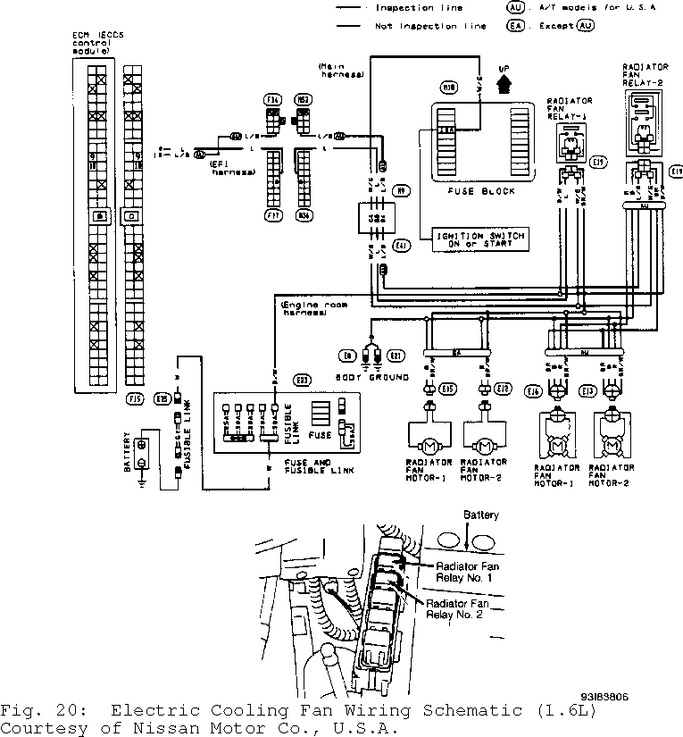
5) Disconnect ECM harness connector. ECM is located under center of instrument panel. Check continuity between ECM harness connector terminal No. 9 (Blue wire) and radiator fan relay No. 1 harness connector terminal No. 1 (Blue wire). See Figs. 5, 6 and 20. Continuity should exist. If continuity exists, go to next step. If continuity does not exist, repair open in Blue wire or connectors between ECM and relay.
6) Check radiator fan relay No. 1. See RELAYS under COMPONENT TESTING. Replace relay as necessary. If relay is okay, check fan motors. See RADIATOR FAN MOTOR under COMPONENT TESTING. Replace motor as necessary. If fan motor is okay, check ECM and ECM harness connector for damage, corrosion or improper connection. Repair as necessary.

Fig. 5: Testing Radiator Fan Low Speed Circuit; Step 1 (1.6L A/T) Courtesy of Nissan Motor Co., U.S.A.

Fig. 6: Testing Radiator Fan Low Speed Circuit; Step 3 & 4 (1.6L A/T) Courtesy of Nissan Motor Co., U.S.A.
Radiator (Cooling) Fan High Speed Control Test (1.6L A/T)
1) Turn ignition off. Disconnect radiator fan relay No. 2. See Fig. 10 and 11. Turn ignition on. Measure voltage between ground and radiator fan relay No. 2 harness connector terminals No. 1 (White/Green wire) and No. 3 (Black/White wire). See Fig. 7, 8 and 9. Battery voltage should be present. If battery voltage is present, go to step 3). If battery voltage is not present, go to next step.
2) Check 10-amp fuse located in fuse box under left instrument panel. Replace fuse as necessary. Check 30-amp fusible link located in fusible link and fuse box next to battery. Check Gray in- line fusible link near battery positive terminal. Replace fusible link(s) as necessary. If fuse and fusible links are okay, repair open in harness or connectors.
3) Turn ignition off. Disconnect radiator fan motor No. 1 and radiator fan motor No. 2 harness connectors. Check continuity between radiator fan motor No. 1 harness connector terminal "b" (Brown wire) and radiator fan relay No. 2 harness connector terminal No. 5 (Brown wire). Check continuity between radiator fan motor No. 2 harness connector terminal "b" (Brown wire) and radiator fan relay No. 2
harness connector terminal No. 5 (Brown wire). See Fig. 7, 8 and 9.
4) Check continuity between radiator fan motor No. 1 harness connector terminal "c" (Red wire) and radiator fan relay No. 2 harness connector No. 6 (Red wire). Check continuity between radiator fan motor No. 2 harness connector terminal "c" (Red wire) and radiator fan relay No. 2 harness connector No. 6 (Red wire). Check continuity between radiator fan relay No. 2 harness connector terminal No. 7 (Black wire) and ground. See Fig. 7, 8 and 9. Continuity should exist in all checks. If continuity exists in all checks, go to next step. If continuity does not exist in one or more check, repair open in appropriate wire or connector.
5) Disconnect ECM harness connector. ECM is located under center of instrument panel. Check continuity between ECM harness connector terminal No. 10 (Blue/Black wire) and radiator fan relay No. 2 harness connector terminal No. 2 (Blue/Black wire). See Figs. 7, 8, 9 and 20. Continuity should exist. If continuity exists, go to next step. If continuity does not exist, repair open in Blue/Black wire or connectors between ECM and relay.
6) Check radiator fan relay No. 2. See RELAYS under COMPONENT TESTING. Replace relay as necessary. If relay is okay, check fan motor(s). See RADIATOR FAN MOTOR under COMPONENT TESTING. Replace motor(s) as necessary. If fan motors are okay, check ECM and ECM harness connector for damage, corrosion or improper connection. Repair as necessary.

Fig. 7: Testing Radiator Fan High Speed Circuit (1.6L A/T) (1 Of 3) Courtesy of Nissan Motor Co., U.S.A.

Fig. 8: Testing Radiator Fan High Speed Circuit (1.6L A/T) (2 Of 3) Courtesy of Nissan Motor Co., U.S.A.
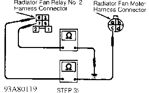
Fig. 9: Testing Radiator Fan High Speed Circuit (1.6L A/T) (3 Of 3) Courtesy of Nissan Motor Co., U.S.A.
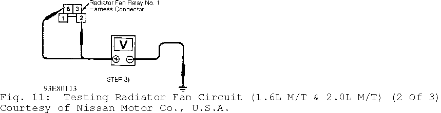
Radiator (Cooling) Fan Control Test (1.6L M/T & 2.0L M/T) 1) For vehicles equipped with A/C, start engine and warm to operating temperature. Set temperature lever to full cold. Turn A/C
switch on. Turn fan switch on. Run engine at idle with A/C on for several minutes. Ensure radiator fan operates. If radiator fan does not operate, turn A/C and fan switches off. Go to step 3). If radiator fan operates, system is functioning properly.
2) For vehicles without A/C, start engine. Keep engine speed at about 2000 RPM until engine is warmed up. Radiator fan should begin to operate during warm-up. If radiator fan does not operate, go to next step. If radiator fan operates, system is functioning properly.
3) Turn ignition off. Disconnect radiator fan relay No. 1. See Fig. 10, 11 and 12. Turn ignition on. Measure voltage between ground and radiator fan relay No. 1 harness connector terminals No. 2 (White/Green wire) and No. 5 (Black/White wire). See Fig. 10, 11 and
12. Battery voltage should be present. If battery voltage is present, go to step 5). If battery voltage is not present, go to next step.
4) Check 10-amp fuse located in fuse box under left instrument panel. Replace fuse as necessary. Check 30-amp fusible link located in fusible link and fuse box next to battery. Check Gray in- line fusible link near battery positive terminal. Replace fusible link(s) as necessary. If fuse and fusible links are okay, repair open in harness or connectors.
5) Turn ignition off. Disconnect radiator fan motor No. 1 and radiator fan motor No. 2 harness connectors. Check continuity between radiator fan motor No. 1 harness connector terminal "a" (Brown/White wire) and radiator fan relay No. 1 harness connector terminal No. 3 (Brown/White wire). Check continuity between radiator fan motor No. 2 harness connector terminal "a" (Brown/White wire) and radiator fan relay No. 1 harness connector terminal No. 3 (Brown/White wire). See Fig. 10, 11 and 12.
6) Check continuity between radiator fan motor No. 1 harness connector terminal "b" (Black wire) and ground. Check continuity between radiator fan motor No. 2 harness connector terminal "b" (Black wire) and ground. See Fig. 10, 11 and 12. Continuity should exist in all checks. If continuity exists in all checks, go to next step. If continuity does not exist in one or more check, repair open in appropriate wire or connector.
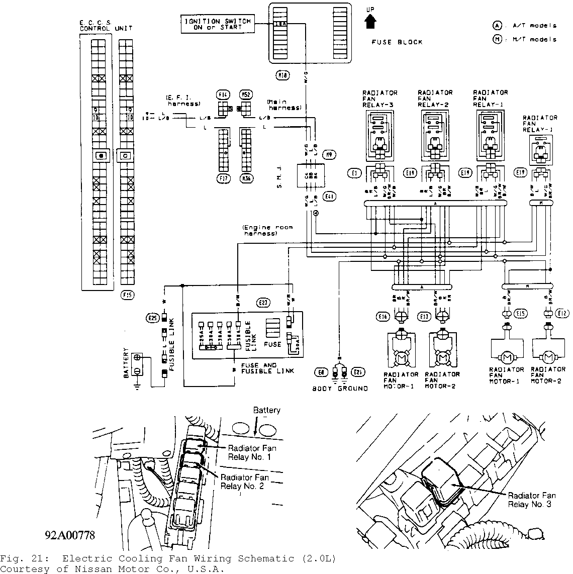
7) Disconnect ECM harness connector. ECM is located under center of instrument panel. Check continuity between ECM harness connector terminal No. 9 (Blue wire) and radiator fan relay No. 1 harness connector terminal No. 1 (Blue wire). See Figs. 10, 11, 12, 20 and 21. Continuity should exist. If continuity exists, go to next step. If continuity does not exist, repair open in Blue wire or connectors between ECM and relay.
8) Check radiator fan relay No. 1. See RELAYS under COMPONENT TESTING. Replace relay as necessary. If relay is okay, check fan motors. See CONDENSER FAN MOTOR TEST. Replace motor as necessary. If fan motor is okay, check ECM and ECM harness connector for damage, corrosion or improper connection. Repair as necessary.


Radiator (Cooling) Fan Control Test (2.0L A/T With A/C)
1) Start engine and warm to operating temperature. Set temperature lever to full cold. Turn A/C switch on. Turn fan switch on. Run engine at idle with A/C on for several minutes. Ensure radiator fan operates at low speed. If radiator fan does not operate at low speed, go to RADIATOR (COOLING) FAN LOW SPEED CONTROL TEST (2. 0L A/T). If radiator fan operates at low speed, go to next step.
2) Turn A/C and fan switches off. Turn ignition off. Disconnect engine coolant temperature sensor. Start engine and ensure radiator fan operates at a speed higher than low speed. If radiator fan does not operate as described, go to RADIATOR (COOLING) FAN HIGH SPEED CONTROL TEST (2.0L A/T). If radiator fan operates as described, system is functioning properly.
Radiator (Cooling) Fan Low Speed Control Test (2.0L A/T)
1) Turn ignition off. Disconnect radiator fan relay No. 1. See Fig. 10, 11 and 12. Turn ignition on. Measure voltage between ground and radiator fan relay No. 2 harness connector terminals No. 1 (White/Green wire), No. 3 (Black/White wire) and No. 6 (White/Black wire). See Fig. 13, 14 and 15. Battery voltage should be present. If battery voltage is present, go to step 3). If battery voltage is not present, go to next step.
2) Check 10-amp fuse located in fuse box under left instrument panel. Replace fuse as necessary. Check 30-amp fusible link located in fusible link and fuse box next to battery. Check Blue in- line fusible link near battery positive terminal. Replace fusible link(s) as necessary. If fuse and fusible links are okay, repair open in appropriate harness or connectors.
3) Turn ignition off. Disconnect radiator fan motor No. 1 and radiator fan motor No. 2 harness connectors. Check continuity between radiator fan motor No. 1 harness connector terminal "a" (Brown/White wire) and radiator fan relay No. 1 harness connector terminal No. 5 (Brown/White wire). Check continuity between radiator fan motor No. 2 harness connector terminal "e" (Brown wire) and radiator fan relay No. 1 harness connector terminal No. 7 (Brown wire). See Fig. 13, 14 and
15.
4) Check continuity between radiator fan motor No. 1 harness connector terminal "d" (Black wire) and ground. Check continuity
between radiator fan motor No. 2 harness connector terminal "h" (Black wire) and ground. See Fig. 13, 14 and 15. Continuity should exist in all checks. If continuity exists in all checks, go to next step. If continuity does not exist in one or more check, repair open in appropriate wire or connector.
5) Disconnect ECM harness connector. ECM is located under center of instrument panel. Check continuity between ECM harness connector terminal No. 9 (Blue wire) and radiator fan relay No. 1 harness connector terminal No. 2 (Blue wire). See Figs. 13, 14, 15 and
21. Continuity should exist. If continuity exists, go to next step. If continuity does not exist, repair open in Blue wire or connectors between ECM and relay.
6) Check radiator fan relay No. 1. See RELAYS under COMPONENT TESTING. Replace relay as necessary. If relay is okay, check fan motors. See RADIATOR FAN MOTOR under COMPONENT TESTING. Replace motor as necessary. If fan motor is okay, check ECM and ECM harness connector for damage, corrosion or improper connection. Repair as necessary.


Radiator (Cooling) Fan High Speed Control Test (2.0L A/T)
1) Turn ignition off. Disconnect radiator fan relays No. 2 and 3. See Figs. 10, 11, 12 and 21. Turn ignition on. Measure voltage between ground and radiator fan relays No. 2 and 3 harness connector terminals No. 1 (White/Green wire) and No. 3 (Black/White wire). See Fig. 7, 8 and 9. Battery voltage should be present. If battery voltage
is present, go to step 3). If battery voltage is not present, go to next step.
2) Check 10-amp fuse located in fuse box under left instrument panel. Replace fuse as necessary. Check 30-amp fusible link located in fusible link and fuse box next to battery. Check Blue in- line fusible link near battery positive terminal. Replace fusible link(s) as necessary. If fuse and fusible links are okay, repair open in appropriate harness or connectors.
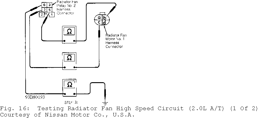
3) Turn ignition off. Disconnect radiator fan motor No. 1 and radiator fan motor No. 2 harness connectors. Check continuity between radiator fan motor No. 1 harness connector terminal "b" (Brown wire) and radiator fan relay No. 2 harness connector terminal No. 5 (Brown wire). Check continuity between radiator fan motor No. 1 harness connector terminal "c" (Red wire) and radiator fan relay No. 2 harness connector No. 7 (Red wire). Check continuity between radiator fan relay No. 2 harness connector terminal No. 6 (Black wire) and ground. See Fig. 16 and 17.
4) Check continuity between radiator fan motor No. 2 harness connector terminal "f" (Brown/White wire) and radiator fan relay No. 3 harness connector terminal No. 5 (Brown/White wire). Check continuity between radiator fan motor No. 2 harness connector terminal "g" (Red wire) and radiator fan relay No. 3 harness connector No. 7 (Red wire). Check continuity between radiator fan relay No. 3 harness connector terminal No. 6 (Black wire) and ground. See Fig. 16 and 17. Continuity should exist in all checks. If continuity exists in all checks, go to next step. If continuity does not exist in one or more check, repair open in appropriate wire or connector.
5) Disconnect ECM harness connector. ECM is located under center of instrument panel. Check continuity between ECM harness connector terminal No. 10 (Blue/Black wire) and radiator fan relays No. 2 and 3 harness connector terminal No. 2 (Blue/Black wire). See Figs. 16, 17 and 21. Continuity should exist. If continuity exists, go to next step. If continuity does not exist, repair open in Blue/Black wire or connectors between ECM and relay(s).
6) Check radiator fan relays No. 2 and 3. See RELAYS under COMPONENT TESTING. Replace relay(s) as necessary. If relays are okay, check fan motor(s). See RADIATOR FAN MOTOR under COMPONENT TESTING. Replace motor(s) as necessary. If fan motors are okay, check ECM and ECM harness connector for damage, corrosion or improper connection. Repair as necessary.

COMPONENT TESTING
Radiator Fan Motor
Disconnect fan motor harness connector(s). Apply battery voltage and ground across fan motor terminals and observe motor operation. See Fig. 18. See RADIATOR FAN MOTOR OPERATION table. If motor does not operate as indicated, replace motor.
RADIATOR FAN MOTOR OPERATION TABLE
�������������������������������������������������������������������������������������������������������������������������������������������
Motor Motor Battery Battery Number Speed Positive (+) Negative (-)
1 ........................ Low ......... "b" ............... "c"
High ..... "a" & "b" ....... "c" & "d" 2 ....................... Low ......... "b" ................ "c"
High ..... "a" & "b" ....... "c" & "d"
�������������������������������������������������������������������������������������������������������������������������������������������

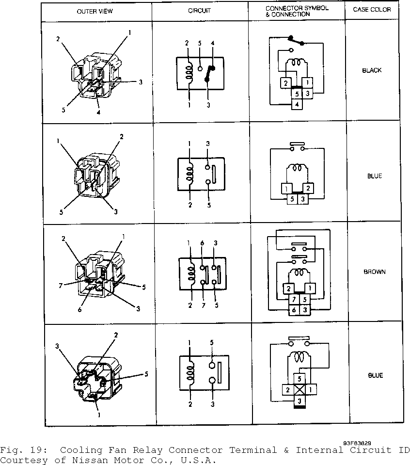
Relays 1) Identify relay type by color. See Fig. 19 Check continuity
between relay terminals No. 3 and 5. On Brown relay, also check continuity between terminals No. 6 and 7. If continuity is present, replace relay. If continuity is not present, go to next step.
2) Apply battery voltage across terminals No. 1 and 2. Check continuity between terminals No. 3 and 5. On Brown relay, also check continuity between terminals No. 6 and 7. If continuity is not present, replace relay. If continuity is present, relay is okay.
WIRING DIAGRAMS