HEATER SYSTEM
�1993 Nissan Sentra
1993 Heater Systems
Pulsar NX & Sentra
DESCRIPTION
HEATER
Heater assembly is contained in a housing beneath instrument panel. Assembly consists of blower motor, heater housing and core, heater valve, and control panel.
VENTILATION
Ventilation is a separate function from heating and is combined with the heating unit to obtain fresh air ventilation when required. Separate selector lever, push button or position setting on mode lever permits fresh air to enter passenger compartment. Blower switch position determines airflow volume.
WARNING: To avoid injury from accidental air bag deployment, read and
carefully follow all SERVICE PRECAUTIONS and DISABLING &
ACTIVATING AIR BAG SYSTEM procedures in AIR BAG RESTRAINT
SYSTEM article in ACCESSORIES & ELECTRICAL section.
OPERATION
MODE SELECTION
Mode lever or push button controls airflow doors (intake, blend-air, heat, defrost and ventilation). Lever setting on control panel determines door positions.
Recirculation/Fresh Door
With door in the open position, outside air flows into heater system after passing through blower motor fan. With door in closed position, inside air is recirculated through heater system.
Ventilation Door
Ventilation door (fresh vent door on some models) permits fresh air to flow from dash panel registers.
Defrost Door
Controls air delivery or defroster outlets when this mode is selected. This separate door opens when mode door closes off floor and dash panel outlets to direct air to windshield.
Blend-Air Door See TEMPERATURE LEVER.
TEMPERATURE LEVER
This lever setting positions blend-air door to direct flow of air through heater core (hot setting), around heater core (cold setting) or mixture of both. The lever also controls opening and closing of heater valve. At any setting except cold, heater valve is open, allowing engine coolant into heater.
BLOWER SWITCH
Switch controls speed of blower motor through resistor assembly. Either a dial knob or control lever may be used to select blower speeds.
ADJUSTMENTS
AIR INTAKE DOOR CABLE
Place air intake door and control lever to recirculation setting. Remove cable retaining clip. Ensure intake door and cable are in full recirculation position. See Fig. 1. Attach control cable retaining clip, and check air intake door operation.
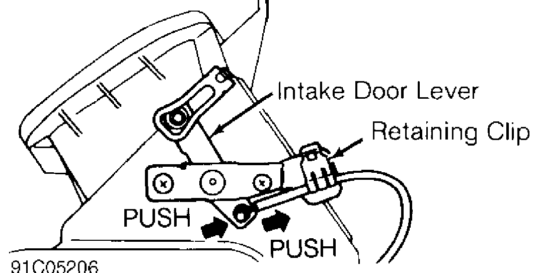
Fig. 1: Adjusting Air Intake Door Cable (NX & Sentra Are Similar) Courtesy of Nissan Motor Co., U.S.A.
FRESH VENT DOOR
Pull fresh ventilation lever down to off position. Pull cable to remove any slack. Attach control cable and retaining clip. Check air intake door operation.
MODE INTAKE DOOR
1) Before installing intake door motor, ensure wiring harness connector of intake door motor is connected. Turn ignition on. Depress recirculation button or move mode lever to recirculation setting.
2) Install intake door motor and lever (if removed). See Fig. 2. Set intake door rod in recirculation position and fasten door rod to holder on intake door lever. Ensure intake door operates properly when recirculation button is pressed on and off or mode lever is moved to and from recirculation setting.
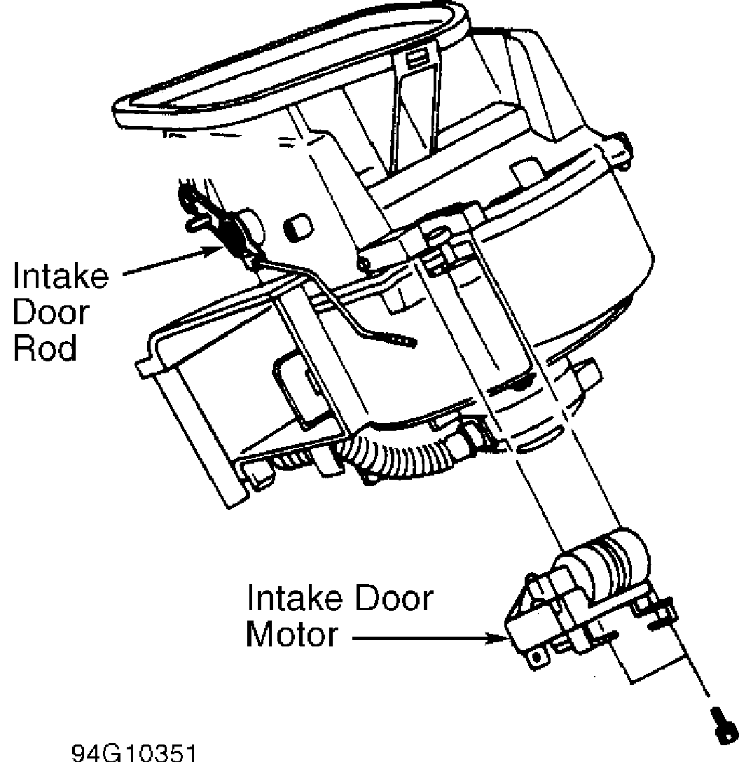
Fig. 2: Adjusting Mode Intake Door (NX & Sentra) Courtesy of Nissan Motor Co., U.S.A.
MODE (AIR) CONTROL CABLE
Place mode selector lever to defrost position. Disconnect control cable and push side link toward cable until it stops. See Fig. 3. Airflow door is now in full defrost position. Connect cable. Pull cable in opposite direction to remove slack, and secure cable using retaining clip.
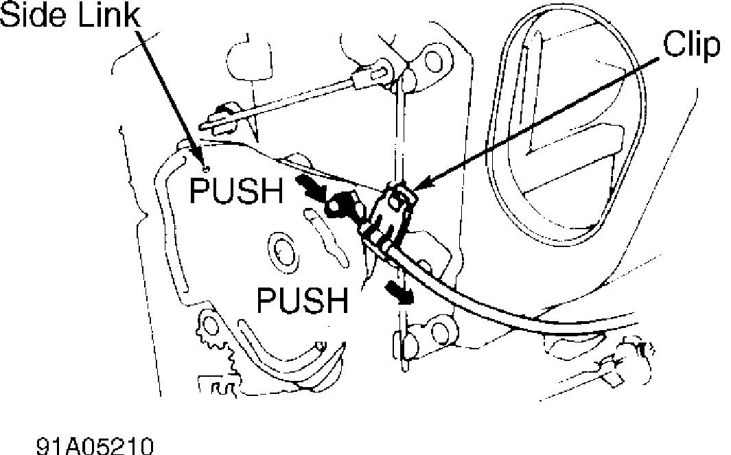
Fig. 3: Adjusting Mode (Air) Control Cable (NX & Sentra Are Similar) Courtesy of Nissan Motor Co., U.S.A.
MODE DOOR
1) Rotate side link clockwise and hold mode door in vent position. See Fig. 4. Install mode door motor on heater assembly, and connect wiring harness connector. Turn ignition on. Depress vent button or move mode lever to vent setting.
2) Install rod of mode door motor to side link rod holder. Depress defrost button (or move mode lever to defrost setting), and ensure side link operates at fully open position. Depress vent button (or move mode lever to vent setting), and ensure side link operates at fully open position.
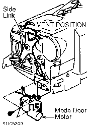
Fig. 4: Adjusting Mode Door Courtesy of Nissan Motor Co., U.S.A.
TEMPERATURE CONTROL CABLE & HEATER VALVE CONTROL ROD
NOTE: Before adjusting heater valve control rod, disconnect temperature control cable from blend-air door. After adjusting control rod, install temperature control cable and adjust it as necessary.
1) Place temperature lever to maximum hot setting. Disconnect temperature control cable from blend-air door lever.
2) Pull heater valve control rod in direction of arrow to obtain .08"(2.0 mm) clearance between ends of rod and link lever. See Fig. 5. Connect rod to door lever. Check operation of air mix door.
3) Push temperature control cable and air mix door lever in direction of arrow. See Fig. 6. Install retaining clip.
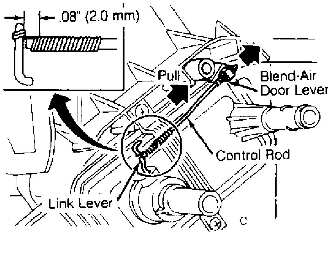
Fig. 5: Adjusting Heater Valve Control Rod (Typical) Courtesy of Nissan Motor Co., U.S.A.
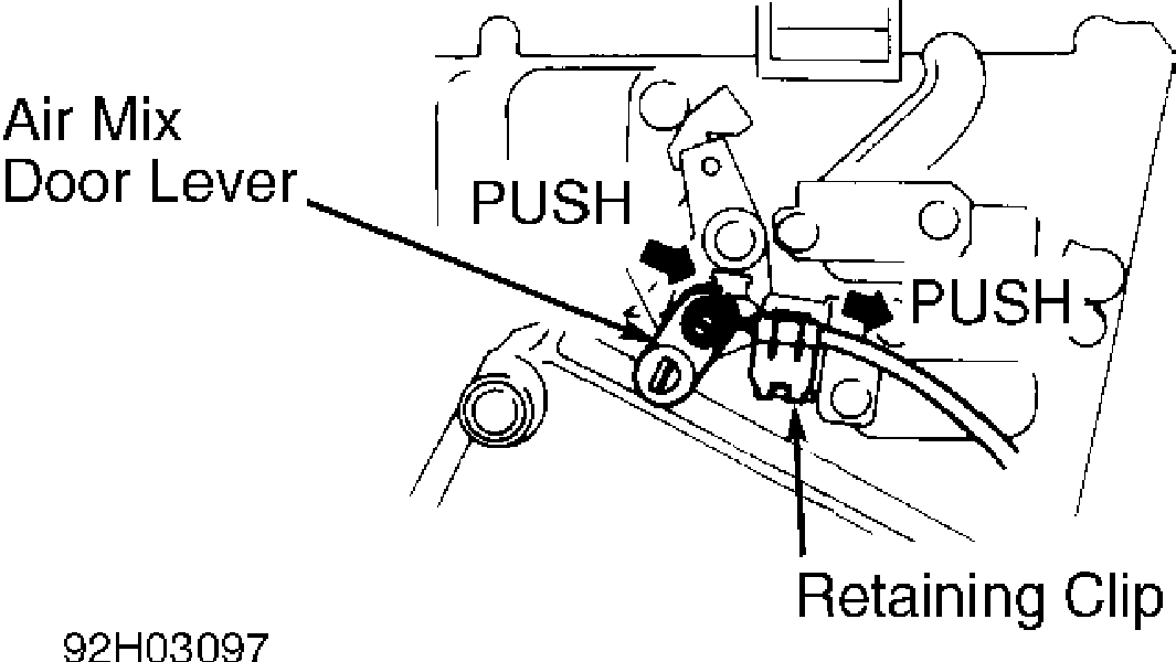
Fig. 6: Adjusting Temperature Control Cable (NX & Sentra Are Similar) Courtesy of Nissan Motor Co., U.S.A.
TROUBLE SHOOTING
NO HOT AIR
Check for malfunctioning engine coolant thermostat, plugged heater core, and low coolant level. Check for malfunctioning blend-air door and heater valve not opening.
NO AIRFLOW TO FLOOR
Check for low blower motor speed, poor electrical connection or blower switch and faulty resistor. Check for malfunctioning floor air door or floor air door actuator.
LOW AIRFLOW TO DEFROSTER
Check for malfunctioning floor/defroster door, faulty door seal and plugged defroster nozzle. Check for leaking duct-to-nozzle connection. Check for defroster door actuator malfunction.
HOT AIR AT ALL TIMES
Check for heater valve not closing. Check for malfunctioning mode door and faulty mode door seal.
NO BLOWER MOTOR OPERATION
Check for blown fuse and melted fusible link. Check for disconnected electrical lead to motor. Check for defective fan switch
and defective blower motor. Check for defective resistor and defective blower relay (if equipped).
CONTROL LEVER DIFFICULT TO OPERATE
Check for inner wire rubbing on outer case end. Check for kinked or bent cable. Check for sticking doors or lever.
OUTSIDE AIR ENTERING WHEN FAN IS OFF
Check air intake door adjustment. Check control cable adjustment. Check for air intake door actuator malfunction.
BLOWER MOTOR/FAN NOISE
Check for loose bolt and foreign objects in blower fan. Check for broken blower fan blades.
TESTING
* PLEASE READ THIS FIRST *
WARNING: To avoid injury from accidental air bag deployment, read and
carefully follow all SERVICE PRECAUTIONS and DISABLING &
ACTIVATING AIR BAG SYSTEM procedures in AIR BAG RESTRAINT
SYSTEM article in ACCESSORIES & ELECTRICAL section.
BLOWER SPEED CONTROL SWITCH
Disconnect blower switch connector. Check for continuity at specified terminals. See TESTING BLOWER SPEED CONTROL SWITCH table. See Figs. 7 and 8. If continuity is not as specified, replace heater control assembly.
TESTING BLOWER SPEED CONTROL SWITCH TABLE
���������������������������������������������������������������������������������������������������
Switch Position Continuity Between Terminals OFF .............................. No Continuity
| 1 | .................................. | 12, 23 & 27 |
|---|---|---|
| 2 | .................................. | 12, 23 & 26 |
| 3 | .................................. | 12, 23 & 25 |
| 4 | .................................. | 12, 23 & 24 |
���������������������������������������������������������������������������������������������������
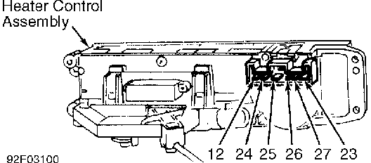
Fig. 7: Blower Switch Connector Terminal ID (Push Button Controls) Courtesy of Nissan Motor Co., U.S.A.
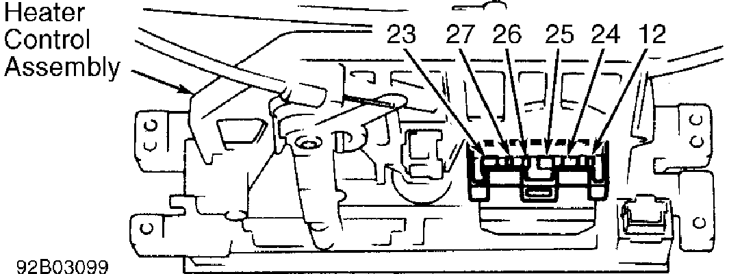
Fig. 8: Blower Switch Connector Terminal ID (Lever Type Controls) Courtesy of Nissan Motor Co., U.S.A.
REMOVAL & INSTALLATION
* PLEASE READ THIS FIRST *
WARNING: To avoid injury from accidental air bag deployment, read and
carefully follow all SERVICE PRECAUTIONS and DISABLING &
ACTIVATING AIR BAG SYSTEM procedures in AIR BAG RESTRAINT
SYSTEM article in ACCESSORIES & ELECTRICAL section.
BLOWER MOTOR
Removal & Installation
Disconnect battery. Disconnect blower wiring harness connector. Disconnect control cable from air intake door. Remove lower dash trim panel (if necessary). Remove blower motor screws. Remove blower motor. To install, reverse removal procedure.
HEATER ASSEMBLY
Removal & Installation
See EVAPORATOR & HEATER CORE ASSEMBLY under REMOVAL & INSTALLATION in MANUAL A/C-HEAT SYSTEM article.
HEATER CONTROL ASSEMBLY
NOTE: Altima removal and installation procedures are not available from manufacturer.
Removal & Installation
1) Remove heater control bezel (if necessary). Remove radio. Remove control unit screws. Remove control cables by unfastening clamps at door levers. Remove heater control assembly bolts.
2) Disconnect wiring harness connector, and remove heater control assembly. To install, reverse removal procedure. Adjust cables, and check system operation.
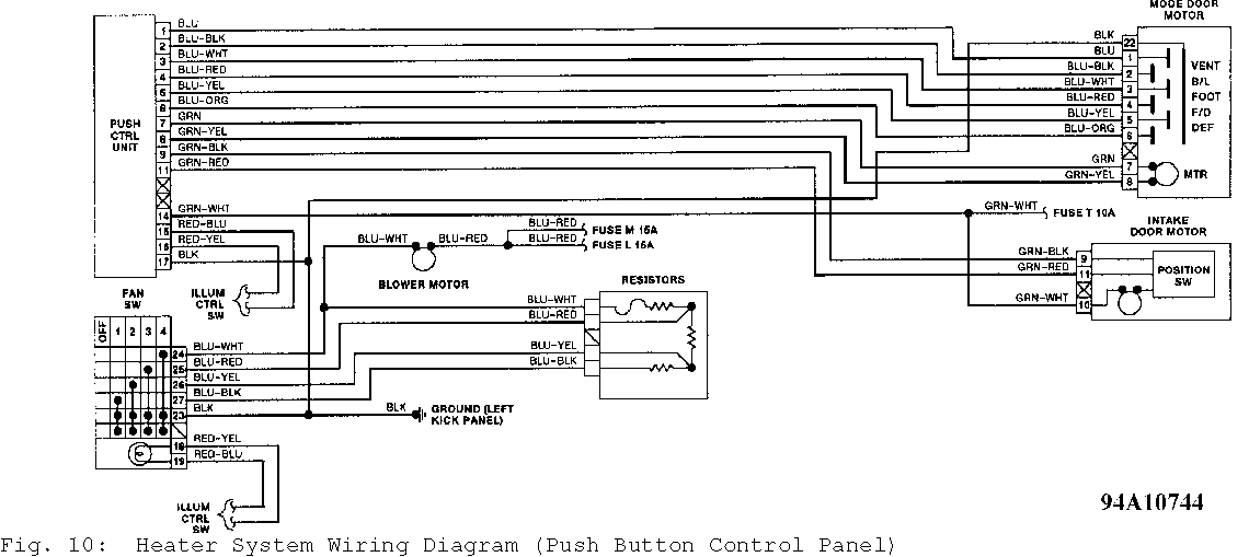
WIRING DIAGRAMS
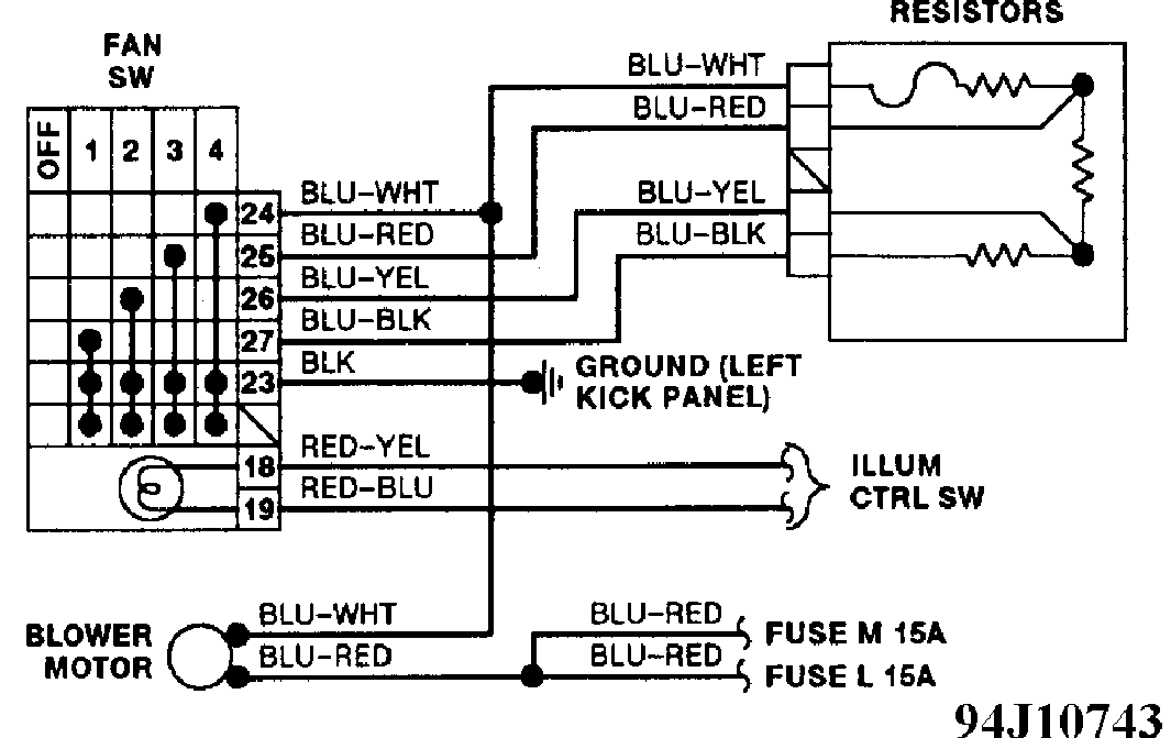
Fig. 9: Heater System Wiring Diagram (Lever Type Control Panel)