
�INSTRUMENT PANEL -ANALOG
�1993 Nissan Sentra
1993 ACCESSORIES/SAFETY EQUIPMENT Nissan Instrument Panels - Analog
Sentra
DESCRIPTION
Analog (needle-type) gauges are mounted on instrument cluster (combination meter). Oil pressure sending switch is located near oil filter.
TESTING
MAIN POWER SUPPLY
Remove instrument cluster. Turn ignition on. Check voltage between ground and specified terminal of instrument cluster connector. See MAIN POWER SUPPLY TEST TERMINALS table. See Fig. 3 or 4. If battery voltage is not present, check for blown fuse, open fusible link, open in wiring harness, faulty ignition relay and/or faulty ignition switch.
MAIN POWER SUPPLY TEST TERMINALS TABLE
�����������������������������������������������������������������������������������������������������������������������
Application Terminal No.
With Tachometer ....................................... 16 Without Tachometer .................................... 15
�����������������������������������������������������������������������������������������������������������������������
BRAKE FLUID LEVEL LIGHT
Remove cap and brake level switch from brake fluid reservoir. Clean any foreign material from terminal connector. Using an ohmmeter, check brake level switch continuity. With brake fluid switch float raised, continuity should not exist. With brake fluid switch float lowered, continuity should exist.
FUEL GAUGE
Remove instrument cluster, leaving connectors attached. Turn ignition on. Connect a jumper wire between ground and fuel gauge terminal on back on instrument cluster for less than 10 seconds. See Fig. 3 or 4. If fuel gauge does not move smoothly from EMPTY to FULL, replace fuel gauge.
FUEL GAUGE SENDING UNIT
Remove sending unit from fuel tank. Measure resistance between terminals "G" (+) and "E" (-) of sending unit connector. See Fig. 1. If resistance values are not about equal to values specified in FUEL GAUGE SENDING UNIT RESISTANCE table, or if values do not change smoothly, replace fuel gauge sending unit.
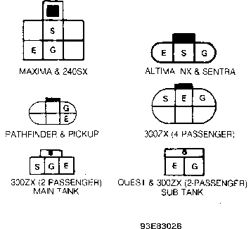
Fig. 1: Fuel Gauge Sending Unit Connector Terminal ID Courtesy of Nissan Motor Co., U.S.A.
FUEL GAUGE SENDING UNIT RESISTANCE TABLE (OHMS)
�����������������������������������������������������������������������������������������������������������������������
Application Full Half Empty
Sentra ............. 4-6 ........ 28-34 ........ 73-85
�����������������������������������������������������������������������������������������������������������������������
LOW FUEL WARNING LIGHT SENSOR
Remove fuel gauge sending unit. Connect 12-volt battery across terminals "E" and "S" of fuel gauge sending unit connector, with a 3.4-watt light bulb connected in series. See Fig. 2. Allow time for light bulb to come on. With sending unit float submerged in gasoline, light should not come on.
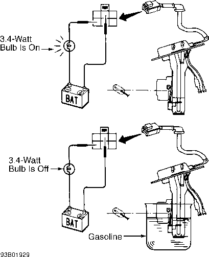
Fig. 2: Testing Low Fuel Warning Light Sensor Courtesy of Nissan Motor Co., U.S.A.
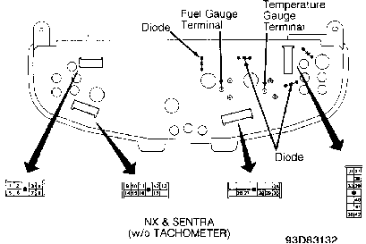
Fig. 3: Rear Views Of Combination Meters (W/O Tachometer) Courtesy of Nissan Motor Co., U.S.A.
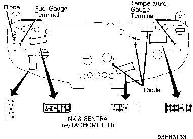
Fig. 4: Rear Views Of Combination Meters (W/ Tachometer) Courtesy of Nissan Motor Co., U.S.A.
OIL PRESSURE SWITCH
Check continuity between terminals of oil pressure switch and body ground. When engine is running, continuity should not exist. When engine is off, continuity should exist.
PARKING BRAKE LIGHT
Disconnect electrical connector from under parking brake handle cover. Using an ohmmeter, check continuity of circuit through connector terminals. With parking brake lever pulled up, continuity should exist. With parking brake lever down, continuity should not exist.
SPEED SENSOR
1) Remove speed sensor from transmission. See Fig. 5. Turn speedometer pinion quickly and measure AC voltage across sensor terminals. If voltage does not toggle at about .5 volt AC, replace speed sensor.
2) Turn ignition on. Spin speed sensor. If .5 volt AC is present, replace speedometer instrument. If .5 volt AC is not present, check continuity of related circuits and speed sensor. Repair as necessary.
CAUTION: Ensure pinion shaft is properly seated when installing
speed sensor. Speed sensor thrusting key should fit into
groove of pinion shaft.
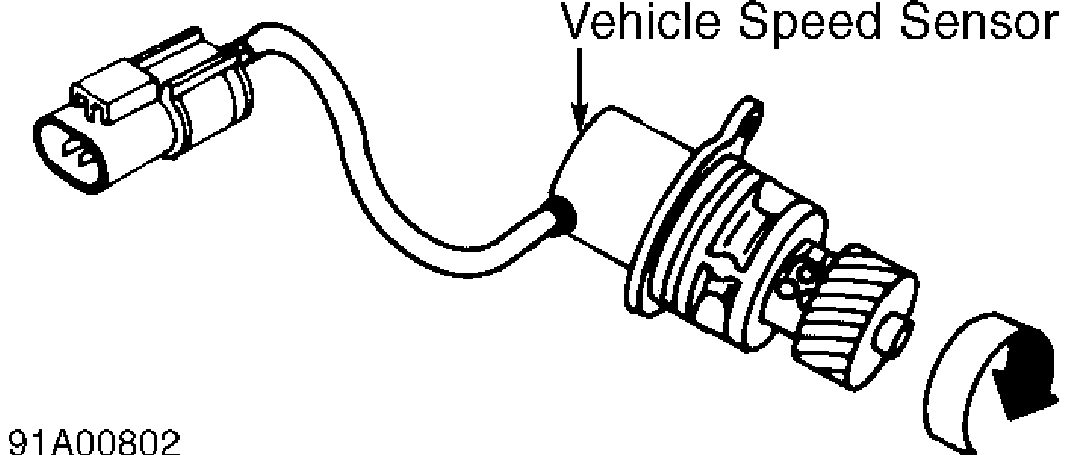
Fig. 5: Testing Vehicle Speed Sensor Courtesy of Nissan Motor Co., U.S.A.
TACHOMETER
NOTE: Tachometer testing for other models is not available.
TEMPERATURE GAUGE
1) Remove instrument cluster, leaving connectors attached. Turn ignition on. Connect a jumper wire between ground and temperature gauge terminal on back of instrument cluster for less than 10 seconds. See Fig. 3 and 4.
2) If temperature gauge does not move smoothly to end of scale, replace gauge.
TEMPERATURE GAUGE SENDING UNIT
Check resistance between ground and temperature sending unit
�� �
terminal. At 140 F (60 C), resistance should be 70-90 ohms. At 212 F
�
(100 C), resistance should be 21-24 ohms.
TIME CONTROL UNIT
1) If time control function for ignition key warning, seat belt warning or wiper delay operates, time control unit power supply and ground circuits are okay. If time control function for all of these components is inoperative, turn ignition off.
2) Time control unit is located behind left end of instrument panel. Check continuity between ground and terminal No. 15 of time control unit connector. See Fig. 6. If there is no continuity, repair ground circuit.
3) If there is continuity, check voltage between time control unit connector terminal No. 15 and indicated terminal in TIME CONTROL UNIT POWER SUPPLY TEST table. If voltage is not as specified, repair appropriate circuit.
TIME CONTROL UNIT POWER SUPPLY TEST TABLE
�����������������������������������������������������������������������������������������������������������������������
Ignition Switch
Terminal No. Position Volts
| 2 (1) | .................... | OFF | ....................... | 0 | ||
|---|---|---|---|---|---|---|
| ACC | ................. | Battery | ||||
| ON | .................. | Battery | ||||
| 5 | ........................ | OFF | ....................... | 0 | ||
| ACC | ....................... | 0 | ||||
| ON | .................. | Battery | ||||
| 9 | ........................ | OFF | ................. | Battery | ||
| ACC | ................. | Battery | ||||
| ON | .................. | Battery | ||||
(1) - Does not apply to 4-door models.
�����������������������������������������������������������������������������������������������������������������������
NOTE: Connectors on some time control units may have more terminals than shown in figure.
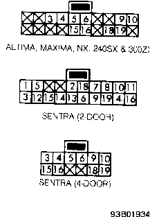
Fig. 6: Time Control Unit Connector Terminal ID Courtesy of Nissan Motor Co., U.S.A.
WARNING BUZZER
Warning Buzzer Test
Remove instrument cluster. Remove warning buzzer from back of instrument cluster. Connect 12-volt battery source across terminals of warning buzzer. Replace warning buzzer if it does not sound.
Headlight Warning Buzzer Inoperative
1) If ignition key warning buzzer operates, go to step 4). If ignition key warning buzzer is inoperative, but interior light comes on, go to step 3). If ignition key warning buzzer and interior light are inoperative, go to next step.
2) Connect time control unit connector. Turn ignition off. Measure voltage between time control unit connector terminals No. 15 and 18. See Fig. 6. With driver door closed, about 12 volts should be present. With driver door open, no voltage should be present. If voltage readings are as specified, go to next step. If voltage readings are not as specified, repair door switch or wiring harness.
3) Connect time control unit connector. Turn ignition off. Measure voltage between time control unit connector terminals No. 15 and 19. See Fig. 6. With driver door closed, about 12 volts should be present. With driver door open, voltmeter needle should deflect intermittently. If voltage readings are not as specified, go to next step. If voltage readings are as specified, check buzzer. See WARNING BUZZER TEST procedure. If buzzer is okay, repair wiring harness.
4) Connect time control unit connector. Turn ignition off. Measure voltage between time control unit connector terminals No. 6
and 15. See Fig. 6. With headlight switch on, about 12 volts should be present. With headlight switch off, no voltage should be present. If voltage readings are as specified, replace time control unit. If voltage readings are not as specified, repair headlight switch or wiring harness.
Ignition Key Warning Buzzer Inoperative
1) If headlight warning buzzer operates, go to step 4). If headlight warning buzzer does not operate, but interior light comes on, go to step 3). If headlight warning buzzer and interior light do not operate, go to step 2).
2) Connect time control unit connector. Turn ignition off. Measure voltage between time control unit connector terminals No. 15 and 18. See Fig. 6. With driver door closed, about 12 volts should be present. With driver door open, no voltage should be present. If voltage readings are as specified, go to next step. If voltage readings are not as specified, repair door switch or wiring harness.
3) Connect time control unit connector. Turn ignition off. Measure voltage between time control unit connector terminals No. 15 and 19. See Fig. 6. With driver door closed, about 12 volts should be present. With driver door open, voltmeter needle should deflect intermittently. If voltage readings are not as specified, go to next step. If voltage readings are as specified, check buzzer. See WARNING BUZZER TEST procedure. If buzzer is okay, repair wiring harness.
4) Connect time control unit connector. Turn ignition off. Measure voltage between time control unit connector terminals No. 10 and 15. See Fig. 6. With key in ignition switch, about 12 volts should be present. With key removed from ignition switch, no voltage should be present.
5) If voltage readings are as specified, replace time control unit. If voltage readings are not as specified, check ignition switch. If ignition switch is okay, repair wiring harness.
Seat Belt Warning Buzzer Inoperative
1) If seat belt warning light goes off or on, go to step 3). If seat belt warning light does not go off or on, go to next step.
2) Disconnect time control unit connector. Turn ignition off. Check continuity between time control unit connector terminals No. 16 and 19. See Fig. 6. With seat belt unfastened, continuity should be present. With seat belt fastened, no continuity should be present. If continuity is as specified, go to next step. If continuity is not as specified, repair seat belt switch or wiring harness.
3) Connect time control unit connector. Turn ignition on. Measure voltage between time control unit connector terminals No. 15 and 19. See Fig. 6. With seat belt unfastened, voltmeter needle should deflect intermittently. With seat belt fastened, about 12 volts should be present. If voltage readings are not as specified, replace time control unit. If voltage readings are as specified, check warning buzzer. See WARNING BUZZER TEST procedure. If buzzer is okay, repair wiring harness.
WARNING LIGHT DIODES
Remove instrument cluster. Check continuity across diode in both directions (polarity). See Fig. 3 or 4. Diode is functioning properly if continuity exists in only one direction.
HEADLIGHT & WIPER SWITCH
Headlight switch and wiper switch are part of combination switch on steering column. See STEERING COLUMN SWITCHES article in the ACCESSORIES/SAFETY EQUIPMENT section.
REMOVAL & INSTALLATION
CAUTION: When removing instrument panel, DO NOT use excessive force to remove plastic parts from retainers or damage may occur. See Fig. 7 for exploded view of instrument panels.
INSTRUMENT CLUSTER
CAUTION: Always disconnect battery negative cable before removing instrument cluster. On vehicles with Head-Up Display (HUD), cover HUD’s reflective surface with cloth or vinyl sheet before removing instrument cluster.
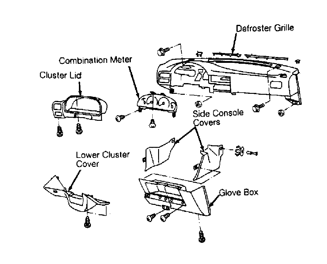
Fig. 7: Exploded View Of Instrument Panel Courtesy of Nissan Motor Co., U.S.A.
WIRING DIAGRAMS
Proceed to chassis WIRING DIAGRAMS article in WIRING DIAGRAMS section.