
�INSTRUMENT PANEL -ELECTRONIC
�1993 Nissan Sentra
1993 ACCESSORIES/SAFETY EQUIPMENT Nissan Electronic Instrument Panels
NX, Sentra
DESCRIPTION & OPERATION
Electronic instrument cluster (combination meter) digitally displays gauge and meter information. A warning buzzer is mounted on back of instrument cluster. A time control unit controls warning buzzer functions and regulates brightness control of segments based on input from brightness control switch.
DIAGNOSTIC TESTING
CAUTION: For all electrical tests, backprobe connector terminals using a Digital Volt-Ohmmeter (DVOM) with a minimum 10-megohm input impedance unless specified otherwise. DO NOT touch contact points of any electrical connector terminals with bare hands.
SPEEDOMETER INDICATES ZERO WHILE DRIVING
1) Raise and support front of vehicle. Disconnect instrument cluster middle connector. See Fig. 1. While turning front wheel slowly, measure AC voltage between connector terminals No. 32 and 34.
2) If voltmeter needle deflects between zero and about .5 volt AC, replace instrument cluster. If voltmeter needle does not deflect between zero and about .5 volt AC, test speed sensor. See SPEED SENSOR under COMPONENT TESTING. If speed sensor is okay, repair wiring harness between speed sensor and instrument cluster.
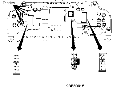
Fig. 1: Instrument Cluster Connector Terminal ID Courtesy of Nissan Motor Co., U.S.A.
SPEEDOMETER CHANGES IRREGULARLY OR IS INCORRECT
Test speed sensor. See SPEED SENSOR under COMPONENT TESTING. If speed sensor is okay, turn ignition off. Disconnect instrument cluster middle connector. See Fig. 1. Disconnect speed sensor connector. Check continuity of wiring harness between speed sensor and instrument cluster connector terminals No. 32 and 34. If harness is okay, replace instrument cluster.
TACHOMETER IS INCORRECT
1) Connect instrument cluster connectors. Start engine. Measure voltage between ground and instrument cluster connector terminal No. 30. See Fig. 1. If voltage is not 1-5 volts, replace instrument cluster. If voltage is 1-5 volts, shut off engine.
2) Disconnect instrument cluster middle connector. Disconnect Powertrain Control Module (PCM) connector. Check continuity between instrument cluster connector terminal No. 30 and PCM connector terminal No. 2 (Light Blue wire). If there is continuity, check PCM. See J - PIN VOLTAGE CHARTS article in ENGINE PERFORMANCE section. If there is no continuity, repair wiring as necessary.
TEMPERATURE GAUGE IS INCORRECT
1) Note which segment of temperature gauge is illuminated. Turn ignition off. Disconnect instrument cluster middle connector. See Fig. 1. Measure resistance between ground and instrument cluster connector terminal No. 27.
2) If resistance is not as specified in TEMPERATURE GAUGE CIRCUIT RESISTANCE TEST table, replace instrument cluster. If resistance is as specified, check temperature gauge sending unit. See TEMPERATURE GAUGE SENDING UNIT under COMPONENT TESTING. If temperature gauge sending unit is okay, check continuity between temperature gauge sending unit and instrument cluster. Repair wiring as necessary.
TEMPERATURE GAUGE CIRCUIT RESISTANCE TEST TABLE
�����������������������������������������������������������������������������������������������������������������������
Illuminated Segment (1) (2) Ohms
| 1 | .............................................. About 203 | |
|---|---|---|
| 4 | ............................................... | About 64 |
| 7 | ............................................... | About 14 |
- (1)
- - Refers to illuminated segment of temperature gauge noted in step 1) of TEMPERATURE GAUGE IS INCORRECT test procedure.
- (2)
- - Measure resistance between ground and instrument cluster connector terminal No. 27.
�����������������������������������������������������������������������������������������������������������������������
FUEL GAUGE IS INCORRECT
1) Note which segment of fuel gauge is illuminated. Turn ignition off. Disconnect instrument cluster middle connector. See Fig. 1. Measure resistance between ground and instrument cluster connector terminal No. 26.
2) If resistance is not as specified in FUEL GAUGE CIRCUIT RESISTANCE TEST table, replace instrument cluster. If resistance is as specified, check fuel gauge sending unit. See FUEL GAUGE SENDING UNIT under COMPONENT TESTING. If fuel gauge sending unit is okay, check continuity between fuel gauge sending unit and instrument cluster. Repair wiring as necessary.
FUEL GAUGE CIRCUIT RESISTANCE TEST TABLE
�����������������������������������������������������������������������������������������������������������������������
Segment (1) (2) Ohms
1 ............................................... About 76 8 ............................................... About 33 14 .............................................. About 12
- (1)
- - Refers to illuminated segment of fuel gauge noted in step 1) of FUEL GAUGE IS INCORRECT test procedure.
- (2)
- - Measure resistance between ground and instrument cluster connector terminal No. 26.
�����������������������������������������������������������������������������������������������������������������������
COMPONENT TESTING
POWER & GROUND CIRCUITS
1) Remove instrument cluster. Turn ignition on. Check voltage between ground and instrument cluster connector. See POWER CIRCUIT TEST table. See Fig. 1. If battery voltage is not present, repair circuit.
2) If battery voltage is present, turn ignition off. Ensure continuity is present between ground and instrument cluster connector terminal No. 25.
POWER CIRCUIT TEST TABLE
�����������������������������������������������������������������������������������������������������������������������
Ignition Switch Terminal No. (1) Position Volts
| 27 | ....................... | OFF | ....................... | 0 | |
|---|---|---|---|---|---|
| 27 | ....................... | ACC | ....................... | 0 | |
| 27 | ....................... | ON | .................. | Battery | |
| 23 | ....................... | OFF | ................. | Battery | |
| 23 | ....................... | ACC | ................. | Battery | |
| 23 | ....................... | ON | .................. | Battery | |
| 31 | ....................... | OFF | ....................... | 0 | |
| 31 | ....................... | ACC | ................. | Battery | |
| 31 | ....................... | ON | .................. | Battery | |
(1) - See Fig. 1 for instrument cluster connector terminal identification.
�����������������������������������������������������������������������������������������������������������������������
FUEL GAUGE SENDING UNIT
Remove fuel gauge sending unit. Measure resistance between Black wire and Green/Blue wire terminals of fuel gauge sending unit connector. See FUEL GAUGE SENDING UNIT RESISTANCE table. If measured resistance is not within specification, replace fuel gauge sending unit.
FUEL GAUGE SENDING UNIT RESISTANCE TABLE
�����������������������������������������������������������������������������������������������������������������������
Float Position Ohms
Full ................................................. 4-6 Half ............................................... 28-34 Empty .............................................. 73-85
�����������������������������������������������������������������������������������������������������������������������
LOW FUEL WARNING LIGHT SENSOR
Remove fuel gauge sending unit from fuel tank. Connect 12volt battery and 3.4-watt light bulb, in series, to fuel gauge sending unit connector. See Fig. 2. Allow time for light bulb to come on. With sending unit float submerged in gasoline, light should not come on.
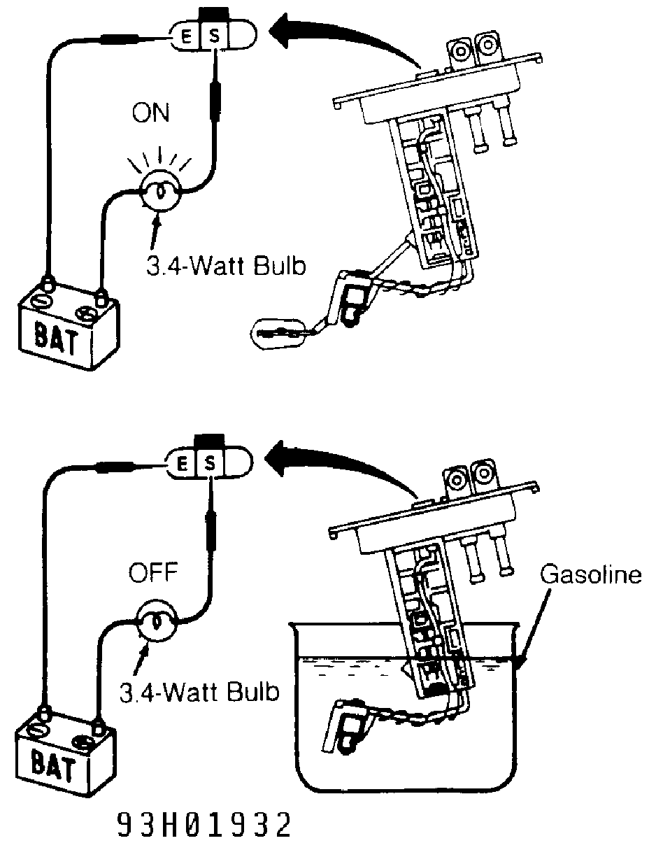
Fig. 2: Testing Low Fuel Warning Light Sensor Courtesy of Nissan Motor Co., U.S.A.
OIL PRESSURE SWITCH
Switch is located on right side of engine. Disconnect switch connector. Check continuity between ground and switch connector terminal. With engine stopped, there should be continuity. With engine running, there should be no continuity.
SEGMENT CHECK
Turn ignition off then on. With ignition on, turn headlight switch off and on more than 10 times. Segments should start to illuminate. To stop segment check, start engine or turn ignition off.
SPEED SENSOR
Turn ignition off. Disconnect electrical connector from speed sensor mounted on transmission. See Fig. 3. Remove speed sensor. Quickly rotate speed sensor gear counterclockwise by hand. Measure AC voltage across speed sensor connector terminals. If voltmeter does not deflect between zero and about .5 volt AC, replace speed sensor.
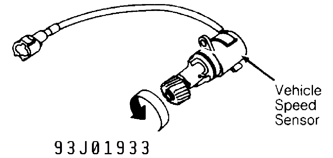
Fig. 3: Testing Vehicle Speed Sensor Courtesy of Nissan Motor Co., U.S.A.
TEMPERATURE GAUGE SENDING UNIT
Temperature gauge sending unit (thermal transmitter) is located on water pipe at flywheel end of cylinder head (1.6L), or on right side of engine (2.0L). Disconnect sending unit connector. Check resistance between ground and sending unit connector terminal. If resistance is not as specified in TEMPERATURE GAUGE SENDING UNIT RESISTANCE table, replace sending unit.
TEMPERATURE GAUGE SENDING UNIT RESISTANCE TABLE
�����������������������������������������������������������������������������������������������������������������������
Coolant Temperature Ohms
140 � F (60 � C) ....................................... 70-90
��
212 F (100 C) ...................................... 21-42
�����������������������������������������������������������������������������������������������������������������������
TIME CONTROL UNIT
1) If time control function for ignition key warning, seat belt warning or wiper delay operates, time control unit power supply and ground circuits are okay. If time control function for all of these components is inoperative, turn ignition off.
2) Time control unit is located behind left end of instrument panel. Check continuity between ground and terminal No. 15 of time control unit connector. See Fig. 4. If there is no continuity, repair ground circuit.
3) If there is continuity, check voltage between time control unit connector terminal No. 15 and indicated terminal in TIME CONTROL UNIT POWER SUPPLY TEST table. If voltage is not as specified, repair appropriate circuit.
TIME CONTROL UNIT POWER SUPPLY TEST TABLE
�����������������������������������������������������������������������������������������������������������������������
Ignition Switch Terminal No. Position Volts
| 2 (1) | .................... | OFF | ....................... | 0 | ||
|---|---|---|---|---|---|---|
| 2 | ........................ | ACC | ................. | Battery | ||
| 2 | ........................ | ON | .................. | Battery | ||
| 5 | ........................ | OFF | ....................... | 0 | ||
| 5 | ........................ | ACC | ....................... | 0 | ||
| 5 | ........................ | ON | .................. | Battery | ||
| 9 | ........................ | OFF | ................. | Battery | ||
| 9 | ........................ | ACC | ................. | Battery | ||
| 9 | ........................ | ON | .................. | Battery | ||
(1) - Does not apply to 2-door hatchback and 4-door models.
�����������������������������������������������������������������������������������������������������������������������
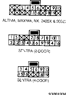
Fig. 4: Time Control Unit Connector Terminal ID Courtesy of Nissan Motor Co., U.S.A.
WARNING BUZZER
Warning Buzzer Test
Remove instrument cluster. Remove warning buzzer from back of instrument cluster. Connect 12-volt battery across specified terminals of warning buzzer. See Fig. 5. Replace warning buzzer if it does not sound.
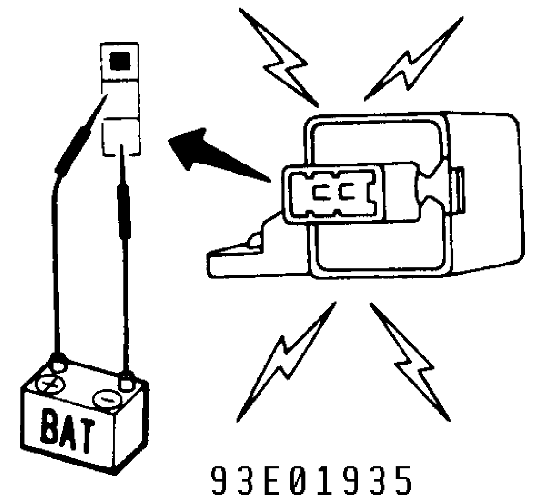
Fig. 5: Testing Warning Buzzer Courtesy of Nissan Motor Co., U.S.A.
Headlight Warning Buzzer Inoperative
1) If ignition key warning buzzer operates, go to step 4). If ignition key warning buzzer is inoperative, but interior light comes on, go to step 3). If ignition key warning buzzer and interior light are inoperative, go to next step.
2) Connect time control unit connector. Turn ignition off. Measure voltage between time control unit connector terminals No. 15 and 18. See Fig. 4. With driver door closed, about 12 volts should be present. With driver door open, no voltage should be present. If voltage readings are as specified, go to next step. If voltage readings are not as specified, repair door switch or wiring harness.
3) Connect time control unit connector. Turn ignition off. Measure voltage between time control unit connector terminals No. 15
and 19. See Fig. 4. With driver door closed, about 12 volts should be present. With driver door open, voltmeter needle should deflect intermittently. If voltage readings are not as specified, go to next step. If voltage readings are as specified, check buzzer. See WARNING BUZZER TEST. If buzzer is okay, repair wiring harness.
4) Connect time control unit connector. Turn ignition off. Measure voltage between time control unit connector terminals No. 6 and 15. See Fig. 4. With headlight switch on, about 12 volts should be present. With headlight switch off, no voltage should be present. If voltage readings are as specified, replace time control unit. If voltage readings are not as specified, repair headlight switch or wiring harness.
Ignition Key Warning Buzzer Inoperative
1) If headlight warning buzzer operates, go to step 4). If headlight warning buzzer does not operate, but interior light comes on, go to step 3). If headlight warning buzzer and interior light do not operate, go to step 2).
2) Connect time control unit connector. Turn ignition off. Measure voltage between time control unit connector terminals No. 15 and 18. See Fig. 4. With driver door closed, about 12 volts should be present. With driver door open, no voltage should be present. If voltage readings are as specified, go to next step. If voltage readings are not as specified, repair door switch or wiring harness.
3) Connect time control unit connector. Turn ignition off. Measure voltage between time control unit connector terminals No. 15 and 19. See Fig. 4. With driver door closed, about 12 volts should be present. With driver door open, voltmeter needle should deflect intermittently. If voltage readings are not as specified, go to next step. If voltage readings are as specified, check buzzer. See WARNING BUZZER TEST. If buzzer is okay, repair wiring harness.
4) Connect time control unit connector. Turn ignition off. Measure voltage between time control unit connector terminals No. 10 and 15. See Fig. 4. With key in ignition switch, about 12 volts should be present. With key removed from ignition switch, no voltage should be present.
5) If voltage readings are as specified, replace time control unit. If voltage readings are not as specified, check ignition switch. If ignition switch is okay, repair wiring harness.
Seat Belt Warning Buzzer Inoperative
1) If seat belt warning light goes off or on, go to step 3). If seat belt warning light does not go off or on, go to next step.
2) Disconnect time control unit connector. Turn ignition off. Check continuity between time control unit connector terminals No. 16 and 19. See Fig. 4. With seat belt unfastened, continuity should be present. With seat belt fastened, no continuity should be present. If continuity is as specified, go to next step. If continuity is not as specified, repair seat belt switch or wiring harness.
3) Connect time control unit connector. Turn ignition on. Measure voltage between time control unit connector terminals No. 15 and 19. See Fig. 4. With seat belt unfastened, voltmeter needle should deflect intermittently. With seat belt fastened, about 12 volts should be present. If voltage readings are not as specified, replace time control unit. If voltage readings are as specified, check warning buzzer. See WARNING BUZZER TEST. If buzzer is okay, repair wiring harness.
WARNING LIGHT DIODES
Remove instrument cluster. Check continuity across diode in both directions (polarity). See Fig. 1. Diode is functioning properly if continuity exists in only one direction.
HAZARD, HEADLIGHT & WIPER SWITCHES
See STEERING COLUMN SWITCHES article in the ACCESSORIES/SAFETY EQUIPMENT section.
REMOVAL & INSTALLATION
INSTRUMENT PANEL
NOTE: Instrument panel removal and installation procedure is not available from manufacturer. For exploded view of instrument panel, see Fig. 6.
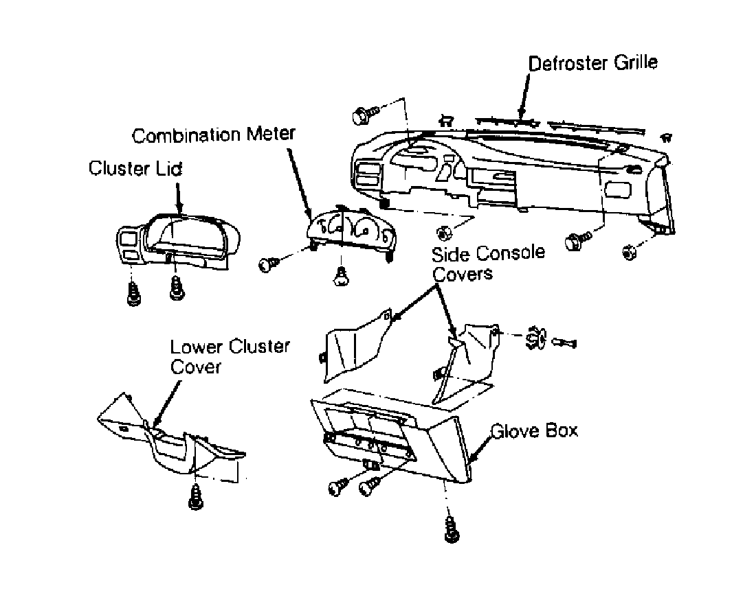
Fig. 6: Exploded View Of Instrument Panel Courtesy of Nissan Motor Co., U.S.A.
WIRING DIAGRAMS
Proceed to appropriate chassis WIRING DIAGRAMS article (for
NX), or WIRING DIAGRAMS article (for Sentra) in WIRING DIAGRAMS section.