
STEERING COLUMN SWITCHES
�1993 Nissan Sentra
1993 ACCESSORIES/SAFETY EQUIPMENT Nissan Steering Column Switches
Altima, Maxima, NX, Pathfinder, Pickup, Quest, Sentra, 240SX, 300ZX
* PLEASE READ THIS FIRST *
WARNING: On Altima, Maxima, NX, Sentra and 300ZX with driver-side air bag, use extreme caution while servicing steering column. Disconnect battery and wait 10 minutes to allow system to electrically discharge before attempting any repair. DO NOT apply electrical power to any component on steering column without disconnecting air bag module or system may be activated.
TESTING
COMBINATION SWITCH
NOTE: Combination switch consists of light switch, wiper switch, cruise control switch and turn signal switch. These switches can be removed and replaced without removing combination switch base.
Remove steering column covers. If necessary, remove switch to
be tested. Use ohmmeter to check continuity across switch connector
terminals as switch is operated. See Figs. 1-7.
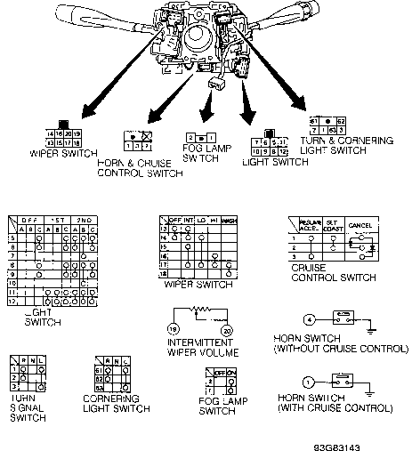
Fig. 1: Checking Continuity Of Combination Switch (Altima) Courtesy of Nissan Motor Co., U.S.A.
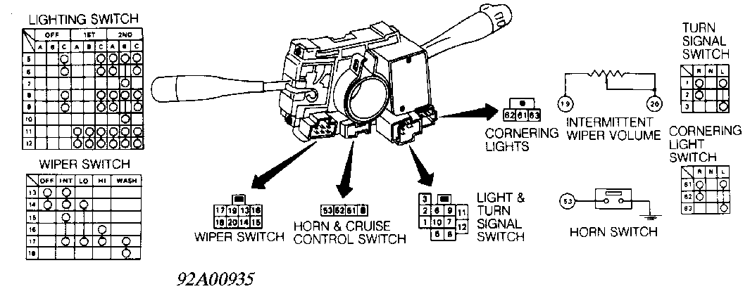
Fig. 2: Checking Continuity Of Combination Switch (Maxima) Courtesy of Nissan Motor Co., U.S.A.
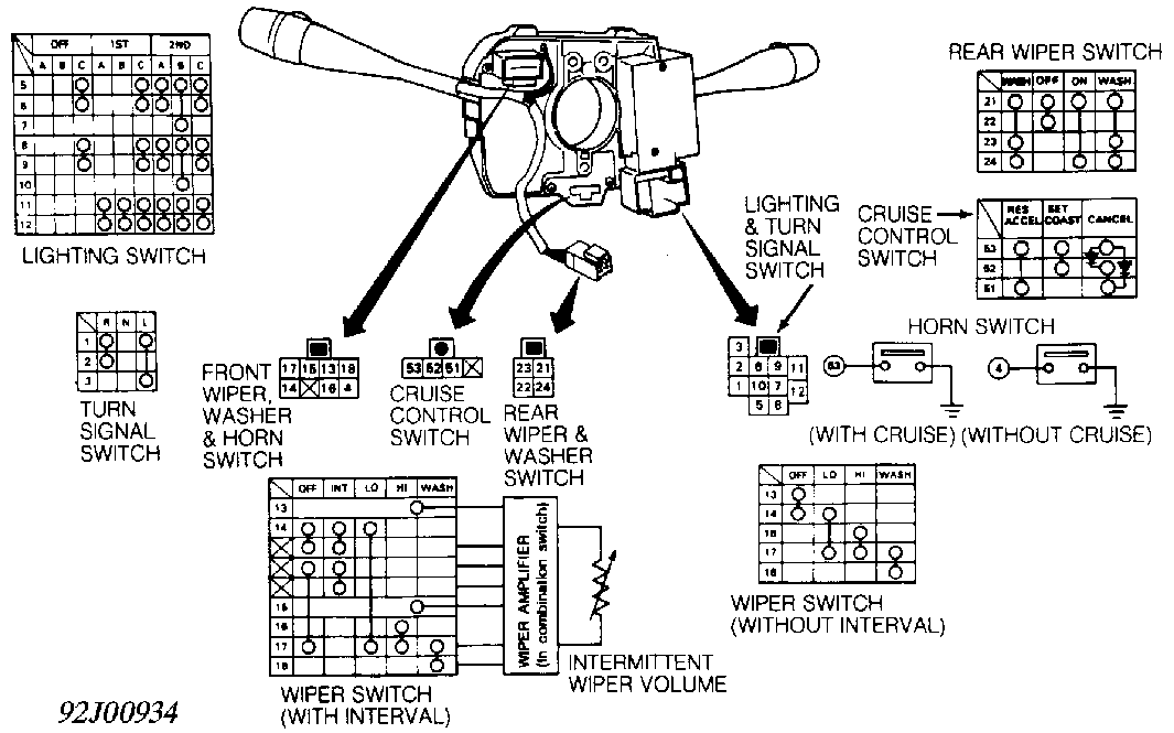
Fig. 3: Checking Continuity Of Combination Switch (NX & Sentra) Courtesy of Nissan Motor Co., U.S.A.
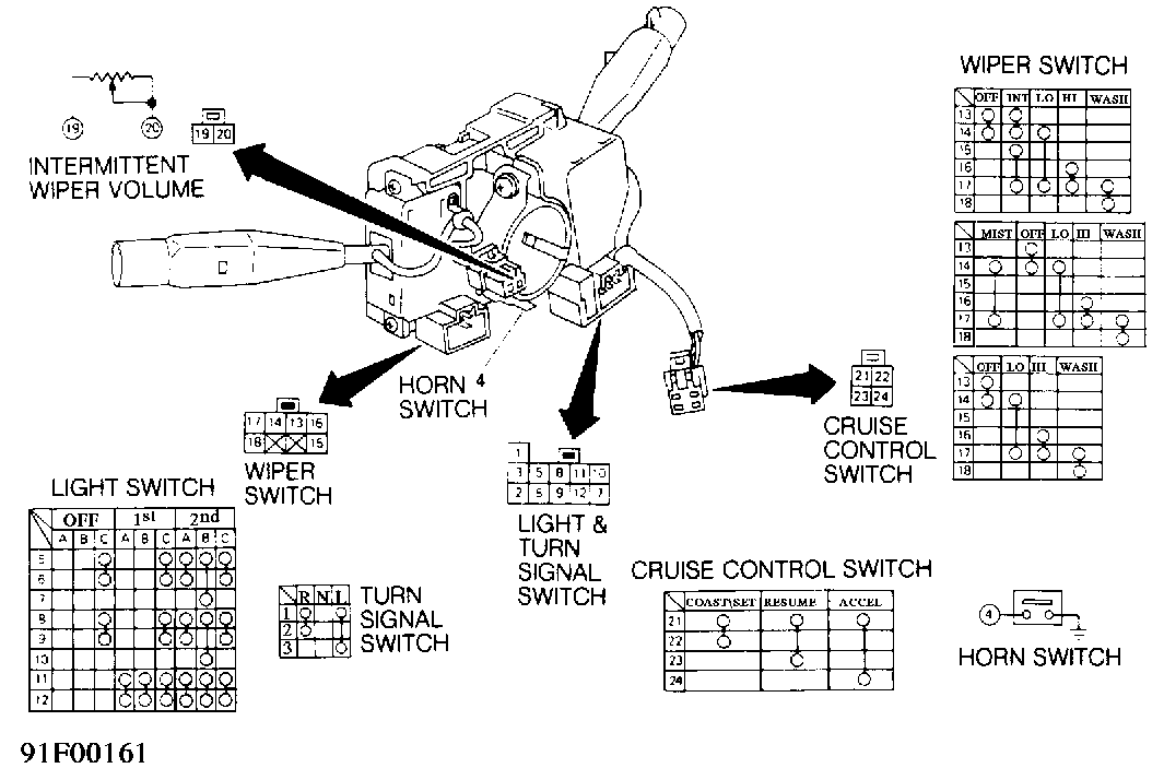
Fig. 4: Checking Continuity Of Combination Sw. (Pathfinder & Pickup) Courtesy of Nissan Motor Co., U.S.A.
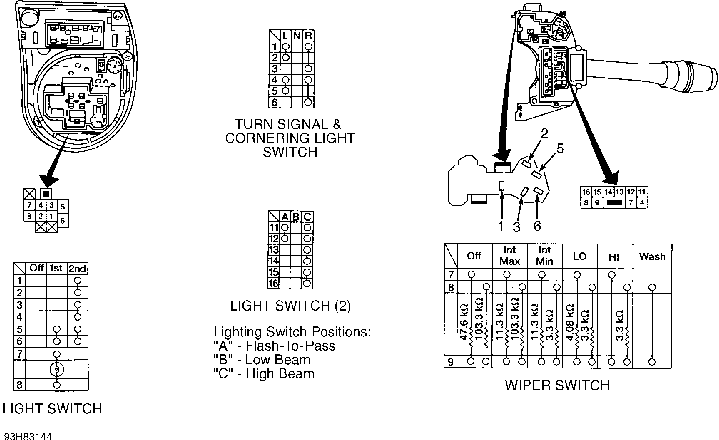
Fig. 5: Checking Continuity Of Combination Switch (Quest) Courtesy of Nissan Motor Co., U.S.A.
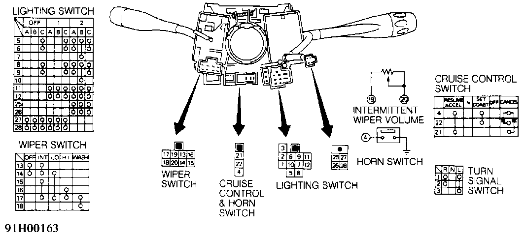
Fig. 6: Checking Continuity Of Combination Switch (240SX) Courtesy of Nissan Motor Co., U.S.A.
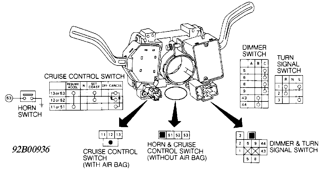
Fig. 7: Checking Continuity Of Combination Switch (300ZX) Courtesy of Nissan Motor Co., U.S.A.
IGNITION SWITCH
Remove ignition switch. See STEERING LOCK & IGNITION SWITCH under REMOVAL & INSTALLATION. Use ohmmeter to check continuity at switch terminals as switch is operated. See Fig. 8.
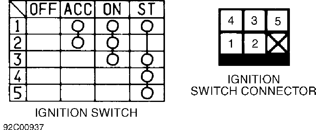
Fig. 8: Checking Continuity Of Ignition Switch Courtesy of Nissan Motor Co., U.S.A.
REMOVAL & INSTALLATION
STEERING WHEEL & HORN PAD
CAUTION: On Altima, Maxima, NX, Sentra and 300ZX with Supplemental Restraint System (SRS), SRS wiring harness is routed near instrument cluster and related parts. All SRS wiring harness connectors are Yellow. DO NOT use electrical test equipment on these circuits. Before working on steering column components, disable air bag system. Proceed to appropriate AIR BAG RESTRAINT SYSTEM article in ACCESSORIES & EQUIPMENT.
Removal & Installation (With Air Bag)
Disarm and remove air bag module. Proceed to appropriate AIR BAG RESTRAINT SYSTEM article in ACCESSORIES & EQUIPMENT section. Remove steering wheel retaining nut. Ensure all wiring harness connectors affecting steering wheel removal are disconnected. Remove steering wheel. See Fig. 9. To install, reverse removal procedure. Install and activate air bag. See AIR BAG RESTRAINT SYSTEM article in the ACCESSORIES/SAFETY EQUIPMENT section.
Removal (Without Air Bag)
1) Disconnect battery ground cable. Remove screws attaching horn button assembly/center pad to steering wheel from behind steering wheel (if equipped).
2) Pull horn button assembly/center pad from steering wheel. Use a cloth-covered screwdriver to pry off horn button assembly/center pad (if necessary). Disassemble horn button assembly (if necessary).
3) Place springs, contacts, horn or cruise control harness connectors and screws in order for reassembly reference. Place wheels in straight-ahead position.
4) Remove steering wheel retaining nut and washer. Mark steering wheel and shaft for reassembly reference. Using a steering wheel puller, remove steering wheel. See Fig. 9.
5) Place steering wheel, cruise control switch (if equipped), canceling cams, springs and slip rings in order for reassembly reference.
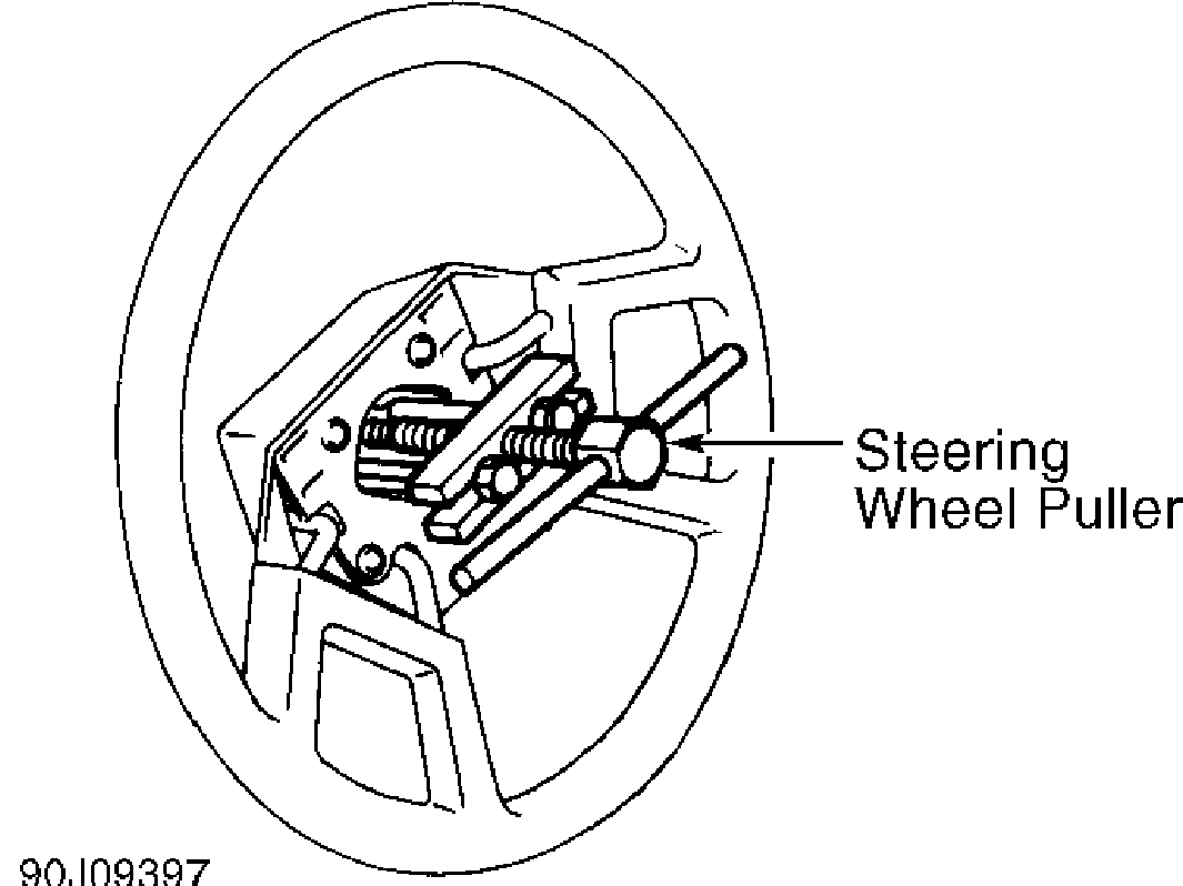
Fig. 9: Removing Steering Wheel Courtesy of Nissan Motor Co., U.S.A.
Installation
1) Coat slip ring contact surfaces with a light electrical grease. Assemble horn button assembly (if necessary). Ensure wheels are in straight-ahead position.
2) Align marks made during removal. Place slip ring, springs, canceling cams, steering wheel, washer and steering wheel retaining nut on shaft.
3) Tighten nut to specification. See TORQUE SPECIFICATIONS table at end of article. To complete installation, reverse removal procedure.
COMBINATION SWITCH
Removal
Remove steering wheel. See STEERING WHEEL & HORN PAD under REMOVAL & INSTALLATION. Remove upper and lower steering column covers. Disconnect combination switch harness connectors. Remove screw securing combination switch clamp to steering column tube. To remove combination switch, push combination switch forward, rotate clockwise and remove.
Installation
To install, reverse removal procedure. Ensure all electrical connections are tight. Check canceling operation of turn signal switch.
STEERING LOCK & IGNITION SWITCH
Removal
1) Remove steering wheel. See STEERING WHEEL & HORN PAD under REMOVAL & INSTALLATION. Remove upper and lower steering column covers. Remove combination switch. Disconnect ignition switch harness connectors.
2) If shear bolt studs are accessible, use a hacksaw to cut a slot into exposed studs. Using a screwdriver, remove studs.
3) If shear bolt studs are recessed or hard to reach with a hacksaw, center punch studs. Using a drill bit and a screw extractor, remove studs. Remove steering lock and ignition switch.
Installation
Install ignition switch. Install new shear bolts. Finger- tighten shear bolts. Ensure proper operation of steering lock and ignition switch. Tighten shear bolts until heads break off. To complete installation, reverse removal procedure.
TORQUE SPECIFICATIONS
TORQUE SPECIFICATIONS TABLE
�����������������������������������������������������������������������������������������������������������������������
Application Ft. Lbs. (N.m)
Steering Wheel Nut ......................... 22-29 (30-39)
�����������������������������������������������������������������������������������������������������������������������