
STEERING COLUMN
�1993 Nissan Sentra
1993 STEERING Nissan - Steering Columns
NX & Sentra
DESCRIPTION
Steering columns are designed to collapse upon impact. A flexible joint and "U" joint(s) connect steering column to steering gear assembly. Some models are equipped with tilt steering. Cruise control, turn signal/headlight, ignition and wiper/washer switches are mounted on column. Switches can be serviced by removing column covers and steering wheel.
WARNING: On NX and Sentra GLE models with driver’s side air bag, use extreme caution while servicing steering column. Disconnect negative battery cable and wait 10 minutes to allow system to electrically discharge before attempting any repair. DO NOT apply electrical power to any component on steering column without disconnecting air bag module or system may be activated.
DISABLING & ACTIVATING AIR BAG SYSTEM
WARNING: After disabling air bag system, wait about 10 minutes before servicing. Air bag system voltage is maintained for about 10 minutes after system is disabled. Servicing system before 10 minutes may cause accidental air bag deployment and possible personal injury.
1) To disable air bag, turn ignition switch to OFF position. Disconnect and shield negative battery cable. Wait 10 minutes before working on or near air bag components.
2) To activate system, reconnect battery. Turn ignition switch to RUN position from passenger side of vehicle. Observe AIR BAG indicator light to ensure system is functioning properly.
REMOVAL & INSTALLATION
WARNING: NX and Sentra GLE models are equipped with Supplemental Restraint System (SRS). SRS wiring harness is routed near instrument cluster and related parts. All SRS wiring harnesses and connectors are Yellow. DO NOT use electrical test equipment on these circuits. Before working on steering column components, disable air bag system. See DISABLING & ACTIVATING AIR BAG SYSTEM.
STEERING WHEEL & HORN PAD
NOTE: Special air bag assembly attaching bolts are coated with a bonding agent. Discard old bolts after removal and replace with new bolts.
Removal (NX and Sentra GLE)
1) Before proceeding, disarm SRS. See DISABLING & ACTIVATING AIR BAG SYSTEM. Remove lower cover from steering wheel. Disconnect air bag assembly connector. Remove right and left side covers from steering wheel. Using Torx Bit (T50H),
remove and discard special air bag assembly attaching bolts. Remove air bag assembly and place on bench with pad side facing upward.
2) Disconnect horn connector and remove nuts. Ensure all other wiring harness connectors affecting steering wheel removal are disconnected. Place steering wheel in straight-ahead position. Remove steering wheel nut and washer. Mark steering wheel and shaft for reassembly reference. Using Steering Wheel Puller (J-25726-A), remove steering wheel. DO NOT overtighten puller bolt on steering wheel.
Installation (NX and Sentra GLE)
To install, reverse removal procedure. Ensure arrow on spiral cable is aligned with alignment mark. See Fig. 2. Tighten steering wheel shaft nut to specifications. See TORQUE S/S table at the end of this article. Use NEW air bag assembly attaching bolts and tighten to 11-18 ft. lbs. (15-25 N.m). Activate air bag system. See DISABLING & ACTIVATING AIR BAG SYSTEM.
Removal (Other Sentra Models)
1) Disconnect battery ground cable. Remove screws attaching horn button assembly/center pad to steering wheel from behind steering wheel.
2) Pull horn button assembly/center pad from steering wheel. Use a cloth-covered screwdriver to pry off horn button assembly/center pad (if necessary). Disassemble horn button assembly (if necessary).
3) Place springs, contacts, horn or cruise control harness connectors (if equipped) and screws in order for reassembly reference. Place wheels in straight-ahead position.
4) Remove steering wheel nut and washer. Mark steering wheel and shaft for reassembly reference. Using a steering wheel puller, remove steering wheel.
5) Place steering wheel, cruise control switch (if equipped), canceling cams, springs and slip rings in order for reassembly reference.
Installation (Other Sentra Models)
1) Coat slip ring contact surfaces with a dielectric grease. Assemble horn button assembly (if disassembled). Ensure wheels are in a straight-ahead position.
2) Align marks made during removal. Place slip ring, springs, canceling cams, steering wheel, washer and steering wheel nut on shaft. Tighten nut to specification. See TORQUE SPECIFICATIONS table at the end of this article. To complete reassembly, reverse removal procedure.
COMBINATION SWITCH
NOTE: Individual switches can be replaced without removing combination switch assembly from steering shaft.
Removal & Installation (Without Air Bag)
1) Remove steering wheel and horn pad. See STEERING WHEEL & HORN PAD under REMOVAL & INSTALLATION. Remove upper and lower column covers. Disconnect wiring harness connectors at combination switch connectors. To remove combination switch assembly, remove base attaching screw. Turn base while pushing on base clamp. See Fig. 1.
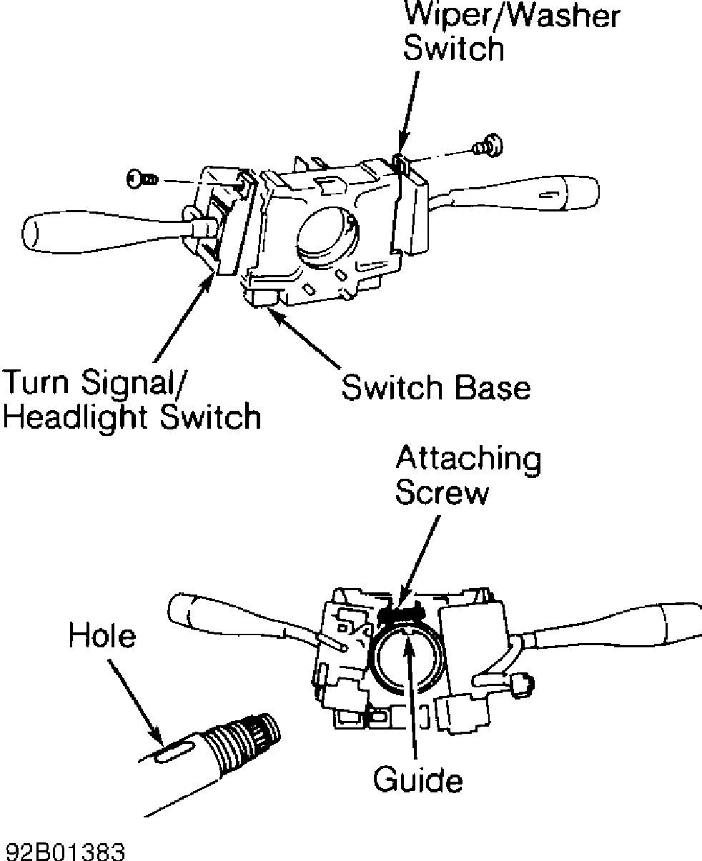
Fig. 1: Removing Combination Switch Courtesy of Nissan Motor Co., U.S.A.
2) To remove individual switches, remove screws attaching cruise control (if equipped), turn signal/headlight and wiper/washer
switch to combination switch base. See Fig. 1. To install, reverse removal procedure.
Removal & Installation (With Air Bag)
1) Before proceeding, disarm SRS. See DISABLING & ACTIVATING AIR BAG SYSTEM. Remove steering wheel and horn pad. See STEERING WHEEL & HORN PAD under REMOVAL & INSTALLATION. Remove upper and lower column covers.
2) Attach stopper to spiral cable to prevent spiral cable from rotating. See Fig. 2. Disconnect spiral cable wire connector, and remove 4 screws attaching spiral cable to combination switch. Remove spiral cable.
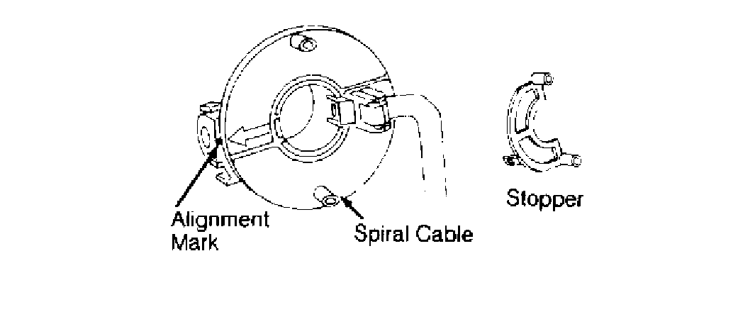
Fig. 2: Aligning Spiral Cable Courtesy of Nissan Motor Co., U.S.A.
3) Disconnect wiring harness connectors at combination switch connectors. To remove combination switch assembly, remove base attaching screw. Turn base while pushing on base clamp. See Fig. 1.
4) To remove individual switches, remove screws attaching cruise control (if equipped), turn signal/headlight and wiper/washer switch to combination switch base. See Fig. 1. To install, reverse removal procedure. Align arrow on spiral cable with neutral position notch. See Fig. 2.
TURN SIGNAL SWITCH
See COMBINATION SWITCH under REMOVAL & INSTALLATION.
IGNITION SWITCH
Removal & Installation
1) Before proceeding, disarm SRS (if equipped). See DISABLING & ACTIVATING AIR BAG SYSTEM. Disconnect battery ground cable. Remove upper and lower column covers. Disconnect wiring harness connector at ignition switch. Center punch 2 shear bolts and carefully drill heads off bolts. Remove shear bolts and ignition switch.
2) Install new ignition switch. Ensure pin on ignition switch is aligned with hole in steering column. Install new shear bolts, and tighten loosely. Insert key and check for proper operation of ignition switch. If switch operates properly, tighten shear bolts until heads break off. To complete installation, reverse removal procedure.
STEERING COLUMN
CAUTION: Applying excessive pressure or causing impact to mainshaft
during service, may cause the column to collapse. DO NOT
attempt to disassemble tilt mechanism (if equipped). If
damage to tilt mechanism or collapsible section is suspected,
replace steering column assembly.
Removal
1) Before proceeding, disarm SRS (if equipped). See DISABLING & ACTIVATING AIR BAG SYSTEM. Disconnect and shield battery ground cable. Place wheels in straight-ahead position. Remove steering wheel and horn pad. See STEERING WHEEL & HORN PAD under REMOVAL & INSTALLATION.
2) Remove lower "U" joint clamp bolt. Remove upper and lower column covers. Disconnect wiring harness connectors to combination switch, ignition switch and spiral cable (if equipped). Remove heater ducts, lower column bracket bolts and floor plate/dust boot bolts.
3) Using a punch, mark pinion shaft to "U" joint for reassembly reference. Remove upper column bracket bolts. To remove column, carefully pull steering column toward passenger compartment.
Inspection
If steering wheel does not rotate smoothly, check column bearings for wear. Ensure bearings are lubricated with grease. Check jacket tube for deformation. If vehicle has been in a collision, check steering column dimension "A". See STEERING COLUMN DIMENSIONS table. See Fig. 3. If measurement is not within specified length, replace steering column as an assembly.
STEERING COLUMN DIMENSIONS TABLE
�����������������������������������������������������������������������������������������������������������������������
| Models | (1) Dimension "A" - In. (mm) | |
|---|---|---|
| NX & Sentra | ||
| With Air Bag ................. | 21.11-21.17 (536.2-537.8) | |
Without Air Bag .............. 20.99-21.06 (533.2-534.8)
(1) - Use appropriate measuring points. See Fig. 3.
�����������������������������������������������������������������������������������������������������������������������
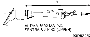
Fig. 3: Steering Column Measuring Points Courtesy of Nissan Motor Co., U.S.A.
Installation
1) Ensure wheels are in straight-ahead position. Insert steering column assembly through floor opening from passenger compartment side of vehicle. Ensure pinion shaft-to-"U" joint punch marks are in correct alignment.
2) Connect lower "U" joint to pinion. Position steering column upper bracket, lower bracket (if equipped) and floor bracket/dust boot.
3) Finger tighten upper column bracket bolts to support column. Install and tighten lower "U" joint bolt. Tighten upper and lower column bracket nuts and bolts to specification. See TORQUE SPECIFICATIONS table at the end of this article.
4) Connect combination switch, ignition switch and spiral cable (if equipped) wiring harness connectors. Install heater ducts and upper and lower column covers. Install steering wheel.
5) Tighten steering wheel nut. Install horn pad. Check operation of horn, ignition switch and combination switch. Turn wheel lock-to-lock to check centering and turning ease.
OVERHAUL
NOTE: Refer to appropriate illustration when overhauling steering column. See Figs. 4.
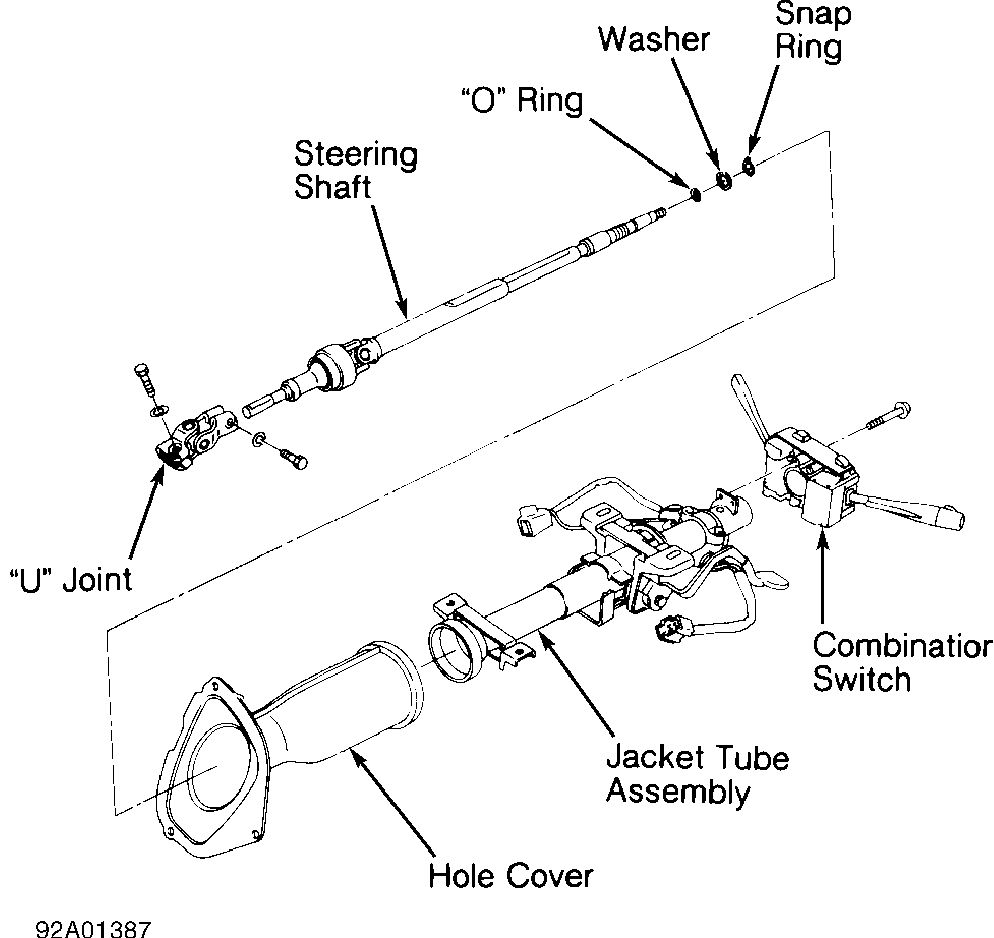
Fig. 4: Exploded View Of Steering Column (NX & Sentra) Courtesy of Nissan Motor Co., U.S.A.
TORQUE SPECIFICATIONS
TORQUE SPECIFICATIONS TABLE
�����������������������������������������������������������������������������������������������������������������������
Application Ft. Lbs. (N.m)
Air Bag Assembly Bolt (All Models) (1) ..... 11-18 (15-25) Lower Column Bracket Nut ................... 11-14 (15-19) Lower "U" Joint Bolt (All Models) .......... 17-22 (23-30) Steering Wheel Nut (All Models) ............ 22-29 (30-39) Upper Column Bracket Bolt (All Models) ..... 10-14 (13-19)
INCH Lbs. (N.m)
Floor Plate Mounting Nut ..................... 35-44 (4-5)
(1) - Air bag assembly attaching bolts are coated with a bonding agent. Discard old bolts after removal and replace with new bolts.
�����������������������������������������������������������������������������������������������������������������������