
�STEERING SYSTEM -MANUAL RACK & PINION
�1993 Nissan Sentra
1993 STEERING Nissan Manual Rack & Pinion
NX, Sentra
DESCRIPTION & OPERATION
Steering gear assembly is a manual rack and pinion type. Unit is mounted to frame by brackets with rubber grommets. Steering shaft is attached to pinion shaft by a "U" joint. Backlash is held to zero by retainer and plunger spring. Rack preload is adjustable.
LUBRICATION
Rack and pinion assembly contains prelubricated sealed bearings.
ADJUSTMENTS
For adjustment procedures, see OVERHAUL.
REMOVAL & INSTALLATION
MANUAL RACK & PINION
Removal & Installation
1) Raise and support vehicle. Remove tie rod end cotter pins and nuts. Using tie rod end puller, separate tie rod end from steering knuckle.
2) Loosen steering gear mounting bolts. Remove steering shaft "U" joint-to-pinion shaft clamp bolt. Remove steering gear with tie rods. To install, reverse removal procedure. Check and adjust wheel alignment. See WHEEL ALIGNMENT SPECIFICATIONS & PROCEDURES article in the WHEEL ALIGNMENT section.
OVERHAUL
MANUAL RACK & PINION
Disassembly
1) Clamp steering gear assembly in a soft-jawed vise. Remove outer tie rods and lock nuts from tie rod inner sockets. Remove boot wire clips and pull boots away from housing. Flatten tab lock washers. Loosen tie rod inner socket and unscrew tie rods from rack. See Fig. 3.
2) Remove adjusting screw lock nut and adjusting screw. Remove plunger spring and rack retainer from housing. Remove dust cover from top of rear cover. See Fig. 1.
3) Remove rear cover lock nut and dust seal. Using Wrench (KV48102000), unscrew rear cover. Pull pinion shaft and bearing from housing. Slide steering rack toward pinion end of housing to remove. Press bearing from pinion shaft.
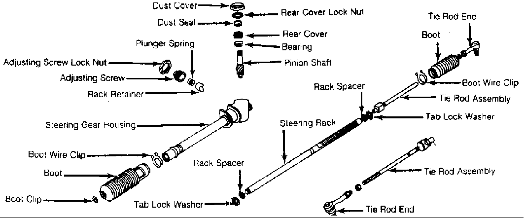
Fig. 1: Exploded View Of Manual Rack & Pinion Steering Gear Courtesy of Nissan Motor Co., U.S.A.
Inspection
Check rack and pinion gear for wear or damage. Inspect tie rod inner socket for excessive looseness. If excessive looseness is found in tie rod inner socket, replace tie rod assembly. Replace any parts that show signs of excessive wear or damage. Replace all oil seals.
Reassembly & Adjustment
1) Press bearing onto pinion shaft. Place steering gear housing in a soft-jawed vise. Grease rack teeth and friction surfaces of rack. Install rack into housing from pinion shaft side. Ensure rack teeth are facing correct direction.
2) Grease and install pinion shaft and bearing. Ensure pinion teeth and rack teeth mesh properly. Ensure rack protrudes equally from each end of housing. Install guide clip on pinion shaft in neutral position (within 6 degrees of a right angle to housing). Apply adhesive to threads of rear cover.
3) Using Wrench (KV48102000), install rear cover. Ensure pinion assembly rotates smoothly. Install rear cover lock nut. Grease inner lips of dust seal. Wrap pinion shaft end with tape to prevent damage to shaft end during installation of dust seal and dust cover. Install dust seal and dust cover.
4) Grease steering gear retainer. Insert gear retainer and plunger spring into housing. Install adjusting screw. Apply liquid sealant around lock nut and install lock nut. Set gears to neutral position. Tighten adjusting screw to 87 INCH lbs. (9.8 N.m). Loosen adjusting screw. Retighten adjusting screw to 87 INCH lbs. (9.8 N.m).
5) Using Socket (KV48101100) and an INCH-lb. torque wrench, check pinion shaft rotating torque. Rotate pinion shaft 100 degrees to each side of center position. Pinion shaft rotating torque should be 6.1-10.4 INCH lbs. (.7-1.2 N.m). See Fig. 2. Holding adjusting screw in position, tighten lock nut to 29-43 ft. lbs. (39-58 N.m).
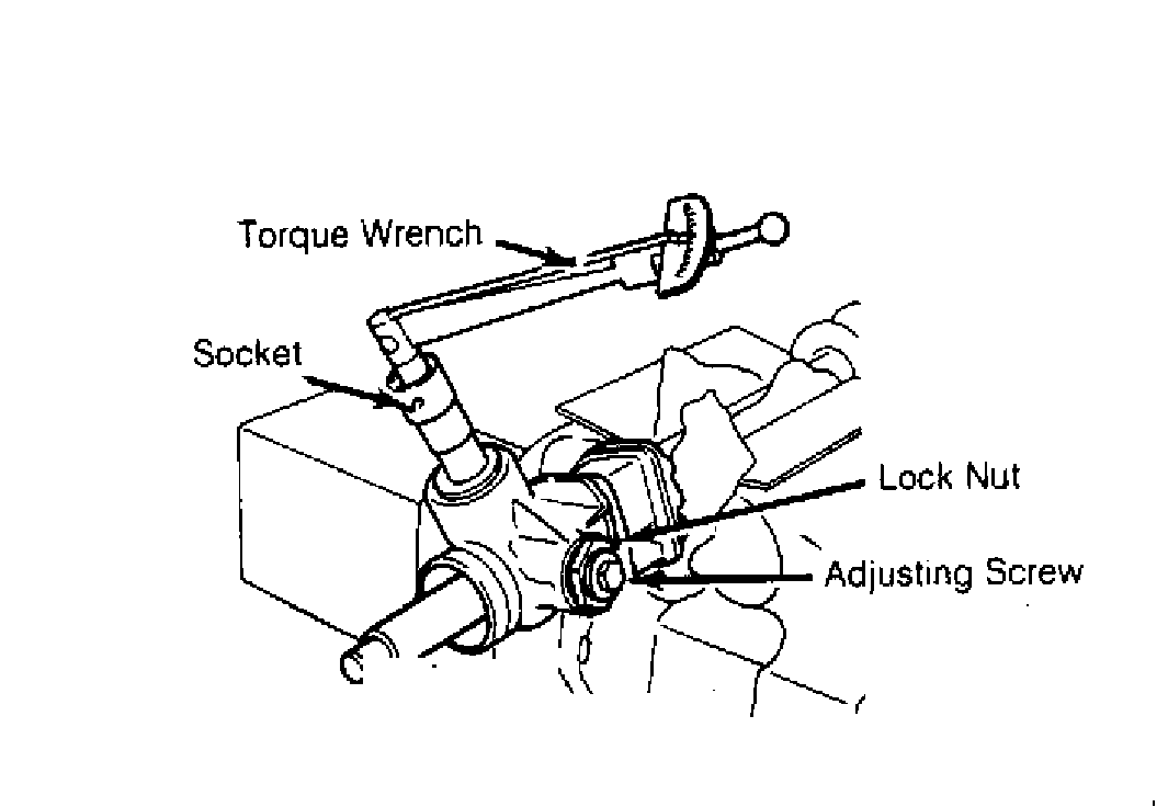
Fig. 2: Measuring Pinion Shaft Rotating Torque Courtesy of Nissan Motor Co., U.S.A.
6) Pinion shaft rotating torque should not fluctuate more than 2.6 INCH lbs. (.3 N.m) within 100 degrees of center position or more than 4.3 INCH lbs. (.5 N.m) outside 100-degree range. If pinion shaft rotating torque is not within specification, replace plunger spring. Different springs are available to allow more or less preload. If pinion shaft rotating torque is still not within specification, replace gear assembly.
7) Install rubber boot and clamp onto tie rod. Apply sealer to threads and install tie rod inner socket assembly onto rack. Bend tab lock washer over at least 2 flats of inner socket. See Fig. 3. Pull boot up onto gear housing. Apply sealer between boot and housing.
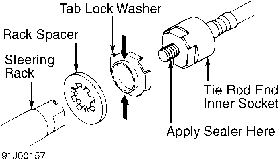
Fig. 3: Installing Rack Spacer & Tab Lock Washer Courtesy of Nissan Motor Co., U.S.A.
8) Wrap wire clip around boot 2 times and twist to install. See Fig. 4. Position wire clip to rear of vehicle on gear housing to
avoid interference. Bend twisted end of wire clip diagonally to avoid contact with boot. Install tie rod end lock nut onto inner tie rod. Install tie rod end onto inner tie rod.
9) Ensure that at least one inch of tie rod end is threaded onto tie rod. Repeat procedure for opposite tie rod assembly. Adjust tie rod length so that distance from outer side of lock nut to end of boot mounting groove is 7.24" (184 mm). See Fig. 5. Tighten lock nut.
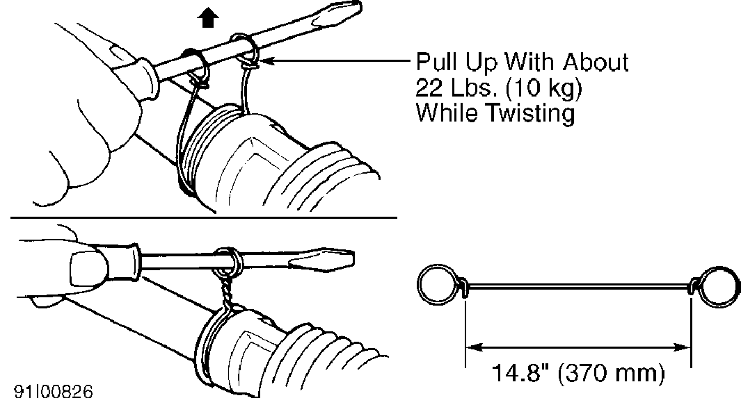
Fig. 4: Installing Boot Wire Clips Courtesy of Nissan Motor Co., U.S.A.
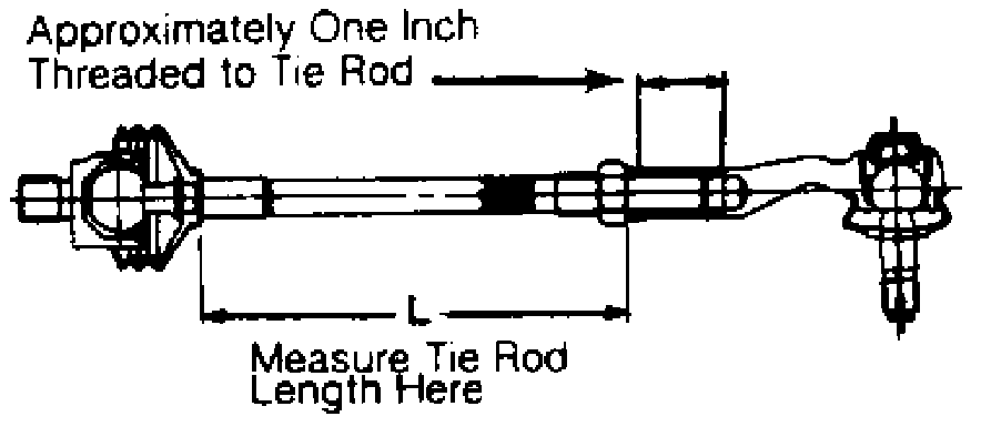
Fig. 5: Measuring Tie Rod Length Courtesy of Nissan Motor Co., U.S.A.
TORQUE SPECIFICATIONS
TORQUE SPECIFICATIONS TABLE
�������������������������������������������������������������������������������������������������������������
Application Ft. Lbs. (N.m)
Gear Housing Mounting Bolt ............ 54-72 (73-98) Pinion Adjusting Screw Lock Nut ....... 29-43 (39-58) Rear Cover Lock Nut ................... 36-51 (49-69) Tie Rod End Lock Nut .................. 27-34 (37-46) Tie Rod End Nut ....................... 22-29 (29-39) Tie Rod Inner Socket-To-Rack .......... 58-72 (78-98) "U" Joint Clamp Bolt .................. 17-22 (24-29)
�������������������������������������������������������������������������������������������������������������