�STEERING SYSTEM -POWER RACK & PINION
�1993 Nissan Sentra
1993 STEERING Nissan Power Rack & Pinion
NX and Sentra
DESCRIPTION & OPERATION
Power steering system consists of a rack and pinion steering gear, steering pump, fluid reservoir and flexible connecting lines. The belt-driven pump mounts on the front of the engine. The reservoir is remotely mounted. Hydraulic pressure for power-assist is produced by a rotary valve, vane type pump assembly. The pump draws fluid from the reservoir and supplies it to the valve assembly. The rotary valve in the pump valve assembly supplies pressurized fluid to the rack piston.
LUBRICATION
CAPACITY
Fluid capacity is approximately 1 qt. (.9L) for all models.
FLUID TYPE
POWER STEERING FLUID SPECIFICATIONS TABLE
�������������������������������������������������������������������������������������������������������������
Application Fluid Type
All Others ............................ Dexron-II ATF
�������������������������������������������������������������������������������������������������������������
FLUID LEVEL CHECK
Check fluid level when fluid is cold with engine off. To check and fill, remove fluid level gauge from reservoir and check fluid level. Fluid should be between MIN and MAX marks on the gauge dipstick. Add fluid through dipstick opening (as needed), and recheck. DO NOT overfill.
HYDRAULIC SYSTEM BLEEDING
CAUTION: DO NOT hold steering wheel at or near lock position for more than 15 seconds.
1) Raise and support vehicle. While adding fluid, turn steering wheel quickly from lock to lock until fluid level no longer decreases and no bubbles exist.
2) Start engine and allow to idle. Repeat step 1). Perform procedure until fluid level no longer decreases and no bubbles exist.
ADJUSTMENTS
POWER STEERING PUMP BELT
NOTE: Check belt deflection with engine cold.
With engine cold, apply 22 lbs. (10 kg) pressure on belt at
center distance between pulleys and note belt deflection. Adjust belt tension if belt deflection is not within specification. See BELT ADJUSTMENT SPECIFICATIONS table.
BELT ADJUSTMENT SPECIFICATIONS TABLE
�������������������������������������������������������������������������������������������������������������������������������������������
| Used Belt | New Belt | |||
|---|---|---|---|---|
| Model | (1) Deflection - In.(mm) | (1) Deflection - In.(mm) | ||
| NX & Sentra ..... .16-.24 (4.0-6.0) | ............. | .12-.20 (3.0-5.0) | ||
(1) - With 22 lbs. (10 kg) pressure applied midway on longest belt run.
�������������������������������������������������������������������������������������������������������������������������������������������
PINION ROTATING TORQUE & RACK SLIDING FORCE
NOTE: Rack sliding force can be checked with steering gear
installed in vehicle, with tie rods and pinion shaft
disconnected. Perform pinion rotating torque adjustment with
steering gear assembly removed from vehicle.
Pinion Rotating Torque
1) Remove steering gear from vehicle. See POWER RACK & PINION under REMOVAL & INSTALLATION. Install steering gear in soft-jawed vise. Drain fluid from steering gear.
2) Remove lock nut and adjusting screw. See Figs. 6 and 7. Apply locking sealant to threads and install adjusting screw. Lightly tighten adjusting screw lock nut. Tighten adjusting screw to 43-52 INCH lbs. (4.9-5.9 N.m). Loosen adjusting screw, then retighten to 1. 74 INCH lbs. (.20 N.m).
3) Install Torque Adapter (J-26364) and INCH-lb. torque wrench on pinion shaft. See Fig. 1. Move rack over its entire stroke several times. Measure pinion rotating torque within range of 180 degrees from neutral position. Stop gear at point of maximum torque. Remove adapter and torque wrench. Loosen adjusting screw, and then tighten to 43 INCH lbs. (4.9 N.m).
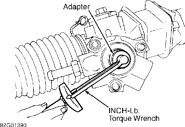
Fig. 1: Measuring Pinion Rotating Torque Courtesy of Nissan Motor Co., U.S.A.
4) Loosen adjusting screw 40-60 degrees, and then tighten lock nut. On all models, ensure adjusting screw does not turn when
lock nut is tightened.
5) Install Torque Adapter (J-26364) and an INCH-lb. torque wrench on pinion shaft. See Fig. 1. Measure turning torque required to rotate pinion. See PINION ROTATING TORQUE SPECIFICATIONS table. If pinion rotating torque is not as specified, repeat step 2). If after readjustment, pinion rotating torque is still not as specified, replace steering gear.
PINION ROTATING TORQUE SPECIFICATIONS TABLE (1)
�������������������������������������������������������������������������������������������������������������
Application INCH Lbs. (N.m)
All Models ................................. 16 (1.9)
(1) - Measure within 100 degrees of neutral position.
�������������������������������������������������������������������������������������������������������������
Rack Sliding Force
1) Position wheels in straight-ahead position. Raise and support vehicle. Remove front wheels. Remove cotter pins and nuts from tie rod ends. Disconnect tie rod ends from steering knuckles. Remove lower steering column joint from pinion shaft. Start engine, and run it at idle. Ensure fluid has reached normal operating temperature.
2) Attach a spring scale at lock nut of tie rod end. Check steering gear for rack sliding force around neutral position of rack stroke. Slowly pull tie rod in a range of 0.5" (11.5 mm). Observe spring scale reading. See RACK SLIDING FORCE SPECIFICATIONS table. If rack sliding force is not within specified range, overhaul steering gear assembly.
RACK SLIDING FORCE SPECIFICATIONS TABLE (1)
�������������������������������������������������������������������������������������������������������������
Application Lbs. (kg)
NX & Sentra ........................... 51-60 (23-27)
(1) - Checked at neutral point of rack stroke.
�������������������������������������������������������������������������������������������������������������
TESTING
HYDRAULIC SYSTEM PRESSURE TEST
NOTE: Ensure power steering belt tension and tire pressure are correct before performing hydraulic system pressure test.
1) Disconnect high pressure hose at power steering pump. Install Pressure Gauge (J-26357) between power steering pump and steering gear. See Fig. 2. Open valve and bleed air from system. See HYDRAULIC SYSTEM BLEEDING under LUBRICATION. Check fluid level.
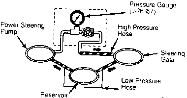
Fig. 2: Installing Pressure Gauge Courtesy of Nissan Motor Co., U.S.A.
NOTE: DO NOT hold steering wheel at or near lock position for more than 15 seconds.
2) Start engine, and allow reservoir fluid temperature to
� �
reach 140-176 F (60-80 C). Set engine speed to 1000 RPM. Check pressure quickly with wheel turned to full-lock position on left and right sides.
3) Compare pressure reading with HYDRAULIC SYSTEM PRESSURE SPECIFICATIONS table. If pressure is lower than specification, slowly close shutoff valve and note pressure. DO NOT close shutoff valve for more than 15 seconds.
4) If pressure now reads within specification, power steering pump is okay and steering gear is defective. If pressure reading is still not within specification, power steering pump is defective. If pressure reading is higher than specification, check power steering pump control valve. Remove pressure gauge and bleed system.
HYDRAULIC SYSTEM PRESSURE SPECIFICATIONS TABLE
�������������������������������������������������������������������������������������������������������������
Application psi (kg/cm � )
NX & Sentra ....................... 1109-1194 (78-84)
�������������������������������������������������������������������������������������������������������������
STEERING WHEEL TURNING TORQUE
1) Park vehicle on dry, level surface. Ensure tire pressure is correct. Apply parking brake. Start and run engine until fluid
� �
temperature is 140-176 F (60-80 C). Attach spring scale to steering wheel.
2) Measure steering wheel turning torque after steering wheel has been turned 360 degrees from center position. Turning torque should be less than 9 lbs. (4.1 kg). If turning torque is not within specification, check rack sliding force to determine condition of steering gear. See PINION ROTATING TORQUE & RACK SLIDING FORCE under ADJUSTMENTS.
REMOVAL & INSTALLATION
POWER STEERING PUMP
Removal
1) If removing pulley, loosen power steering pump pulley nut. Loosen pump adjusting bolts, and remove pump drive belt. Note angle of pressure hose installation on power steering pump.
2) Disconnect high pressure hose from power steering pump. Drain fluid. Remove suction line from pump. Remove pump retaining bolts and pump.
Installation
1) To install, reverse removal procedure. Replace all sealing washers and "O" rings. Lubricate all sealing washers and "O" rings with ATF before installation.
2) Tighten connector bolts to specification. See TORQUE SPECIFICATIONS (POWER STEERING PUMP) table at the end of the article. Adjust belt tension. See POWER STEERING PUMP BELT under ADJUSTMENTS. Fill and bleed system. See HYDRAULIC SYSTEM BLEEDING under LUBRICATION.
POWER RACK & PINION
Removal
1) Raise and support vehicle. Position wheels in straight- ahead position. Note position of hoses on steering gear. Disconnect and mark hoses at steering gear. Drain fluid. Plug hoses and openings in steering gear.
2) Remove tie rod cotter pins and nuts at steering knuckles. Using Ball Joint Separator (HT72520000), separate tie rod ends from steering knuckles.
3) Remove steering column lower joint-to-pinion shaft retaining bolt. With wheels in straight-ahead position, place punch mark on lower joint and pinion shaft for reassembly reference.
4) Remove lower joint from pinion shaft. Remove steering gear mounting bracket retaining bolts. Remove steering gear and linkage.
Installation
1) To install, reverse removal procedure. Install NEW "O" rings on hoses (if equipped). Coat "O" rings with ATF before installation. Ensure proper sized "O" ring is installed. Align reference mark on lower joint and pinion shaft.
2) Tighten nuts and bolts to specification. See TORQUE SPECIFICATIONS (STEERING GEAR) table at the end of the article. Fill and bleed system. See HYDRAULIC SYSTEM BLEEDING under LUBRICATION. Check front wheel alignment if tie rods were removed or steering gear was overhauled. See WHEEL ALIGNMENT SPECIFICATIONS & PROCEDURES article in the WHEEL ALIGNMENT section.
OVERHAUL
POWER STEERING PUMP
NOTE: Disassemble power steering pump to repair leaks only. Replace pump if defective.
Disassembly
1) Ensure pump housing is cleaned before disassembly. Remove pulley nut and pulley. Remove mounting bracket from front of pump (if equipped). Remove suction pipe and "O" ring.
CAUTION: Mark internal components for direction of installation before removal.
2) Remove pulley shaft retaining snap ring. Remove pulley shaft and bearing. Remove oil seal from housing. See Fig. 3. Note seal installation direction.
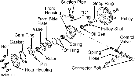
Fig. 3: Exploded View Of Power Steer Pump (Typical) Courtesy of Nissan Motor Co., U.S.A.
3) Remove rear cover bolts. Remove rear cover and gasket. Mark direction of cam ring, rotor and vane for installation reference.
Remove rotor, vanes, cam ring and pins.
4) Remove front side plate and "O" rings. Remove housing spring or wave washers (if equipped). Remove connector, control valve, "O" ring (if equipped) and spring from housing.
Inspection
Inspect components for scoring and damage. Replace pump assembly if components are damaged.
Reassembly
1) Install NEW oil seal, "O" rings and gasket. Coat "O" rings with ATF before installation. Rotor should be installed with punch mark located on face of rotor toward housing side of pump. Install vanes with flat side toward rotor.
2) Install cam ring in alignment with pins. Ensure cam ring properly seats on both pins. To complete installation, reverse removal procedure. Tighten nuts and bolts to specification. See TORQUE SPECIFICATIONS (POWER STEERING PUMP) table at the end of the article.
POWER RACK & PINION
NOTE: Before disassembly of steering gear, measure pinion rotating
torque for reassembly reference. See PINION ROTATING TORQUE
& RACK SLIDING FORCE under ADJUSTMENTS.
Disassembly
1) Remove gear housing tubes. Drain fluid. Remove boot bands and clamps. Measure and record pinion rotating torque. Remove outer tie rods and boots.
2) Pry up staked portion to tie rod inner sockets. Remove tie rod inner sockets. Remove lock plates. Remove rear housing cover. Remove pinion assembly. Remove pinion adjusting screw lock nut and adjusting screw. Remove spring (if equipped), spring disc, washer, spring seat (if equipped) and retainer. See Fig. 8.
3) Drill staked portion of gear housing end. See Fig. 4. Remove end cover assembly. Draw out rack assembly. Using a heat gun, heat rack seal ring to approximately 104 � F (40 � C). Remove rack seal ring. Using a tape-wrapped socket and extension bar, remove center bushing and rack oil seal. DO NOT scratch inner surface of pinion housing.
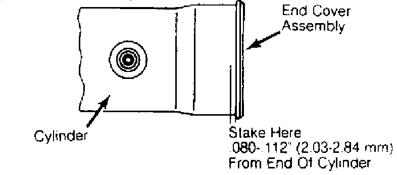
Fig. 4: Positioning Stake Area For Cylinder & End Cover Courtesy of Nissan Motor Co., U.S.A.
Inspection & Reassembly 1) Clean all components in solvent. Blow dry with compressed
air. Replace all oil seals and "O" rings. Inspect boots for damage. Replace if damaged. Inspect all sealing surfaces and pinion bearing for roughness.
2) Inspect tie rod inner socket for end play. Replace tie rod inner socket if end play exists. Inspect steering gear components for damage. Replace damaged components.
3) Using a heat gun, heat rack seal ring to approximately 104 � F (40 � C) and install seal ring into rack. Insert Rack Seal Ring Reformer (KV48104400) from rack gear side and compress rack seal ring to position and secure on rack.
4) Place plastic film into rack oil seal to prevent damage by rack teeth. Insert rack oil seal. Ensure rack oil seal lips face each other. Remove plastic film. Install center bushing and rack oil seal with rack assembly.
5) Tighten end cover assembly. Stake gear housing to cover assembly. See Fig. 4. Set rack gear in neutral position. Measure rack stroke. See Fig. 5. See RACK STROKE SPECIFICATIONS table.
RACK STROKE SPECIFICATIONS TABLE
�������������������������������������������������������������������������������������������������������������
| Application | In. (mm) | |
|---|---|---|
| 1.6L | ................................... | 2.90 (74.0) |
| 2.0L | ................................... | 2.59 (66.0) |
�������������������������������������������������������������������������������������������������������������

Fig. 5: Measuring Rack Stroke Courtesy of Nissan Motor Co., U.S.A.
6) Coat pinion oil seal lip with multipurpose grease. Install NEW pinion oil seal to pinion housing of gear housing. Ensure installed seal lip is facing up. Install NEW pinion bearing adjusting shim(s). Always use same number of shim(s).
7) Using a heat gun, heat pinion seal rings to approximately
��
104 F (40 C) and install on pinion assembly. Ensure pinion seal rings settle properly in valve groove. Apply multipurpose grease to needle bearing roller and oil seal lip. Install pinion assembly into gear housing.
8) Apply multipurpose grease to rear oil seal lip and install in rear housing. Install rear cover cap. See Fig. 6. On NX and Sentra, install retainer, washer and spring disc. Ensure painted end of spring disc is facing outward. Install adjuster screw and adjusting lock nut.
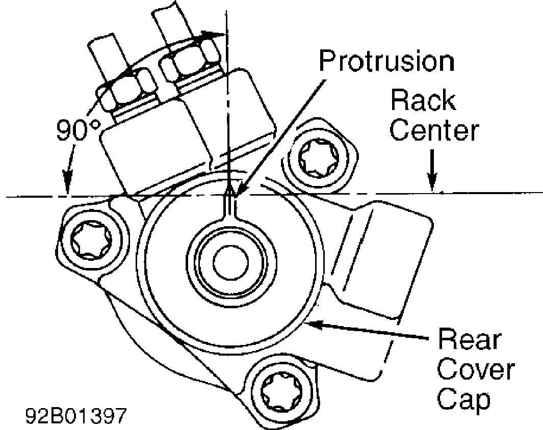
Fig. 6: Installing Rear Cover Cap Courtesy of Nissan Motor Co., U.S.A.
9) On all other models, install retainer, spring seat, washer and spring disc. Ensure painted end of spring disc is facing outward. Install spring, adjusting screw and lock nut.
10) On all models, attach lock plate to tie rod inner socket. Apply locking sealant to inner socket threads. Screw inner socket into rack, and tighten to specification. See TORQUE SPECIFICATIONS (STEERING GEAR) table at the end of the article. Clinch lock plate in 2 places at rack groove. Remove burrs from lock plate (if necessary).
11) Coat contact surfaces between boot and tie rod with grease. Install boot and boot clamps. Ensure boot clamps are facing rear of vehicle when gear housing is in installed position.
12) Install lock nuts and outer tie rods. Measure tie rod length. See Fig. 7. See TIE ROD LENGTH SPECIFICATIONS table. Recheck rack stroke. See RACK STROKE SPECIFICATIONS table. See Fig. 5. If rack stroke is not within specification, recheck procedures performed in steps 6) through 10). Check pinion rotating torque. See PINION ROTATING TORQUE & RACK SLIDING FORCE under ADJUSTMENTS.
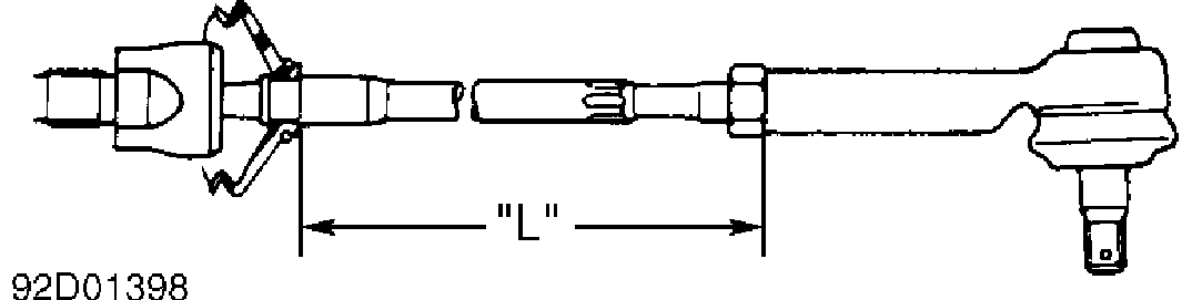
Fig. 7: Measuring Tie Rod Length Courtesy of Nissan Motor Co., U.S.A.
TIE ROD LENGTH SPECIFICATIONS TABLE
�������������������������������������������������������������������������������������������������������������
Application In. (mm) NX & Sentra ............................ 7.24 (184.0)
�������������������������������������������������������������������������������������������������������������
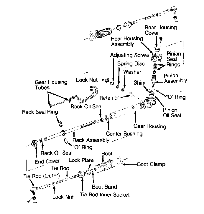
Fig. 8: Exploded View Of Power Rack & Pinion Courtesy of Nissan Motor Co., U.S.A.
TORQUE SPECIFICATIONS
TORQUE SPECIFICATIONS TABLE (POWER STEERING PUMP)
�������������������������������������������������������������������������������������������������������������
Application Ft. Lbs. (N.m)
Control Valve Connector Bolt .......... 51-58 (69-79) Hose Connector Bolt ................... 36-51 (49-69) Pulley Nut ............................ 40-50 (54-68) Rear Cover Bolt ........................ 23-31 (31-42) Suction Pipe Bolt ..................... 10-13 (14-18)
�������������������������������������������������������������������������������������������������������������
TORQUE SPECIFICATIONS TABLE (STEERING GEAR)
�������������������������������������������������������������������������������������������������������������
Application Ft. Lbs. (N.m)
Adjusting Screw Lock Nut .............. 29-43 (39-58) End Cover ............................. 43-54 (58-73) Lower Joint-To-Pinion Shaft Bolt ...... 17-22 (23-30) Rear Housing Cover Bolt ............... 12-15 (16-20) Steering Gear Mounting Bracket Bolt ... 54-72 (73-98) Tie Rod Inner Socket .................. 58-72 (79-98) Tie Rod Lock Nut ....................... 27-34 (37-46) Tie Rod-To-Steering Knuckle Nut ........ 22-29 (30-39)
�������������������������������������������������������������������������������������������������������������