
�SUSPENSION -FRONT
�1993 Nissan Sentra
1993 SUSPENSION Nissan Front
NX & Sentra
DESCRIPTION
All models use a MacPherson strut-type front suspension system. See Fig. 1. Strut assembly consists of a shock absorber and coil spring. Upper end of strut is bolted to upper body of vehicle.
Lower end of strut is bolted to steering knuckle. Steering knuckle is attached to transverse link by a ball joint. Transverse links are attached to suspension member by pivot bolts and compression rod clamp. Stabilizer bar is attached to transverse link.
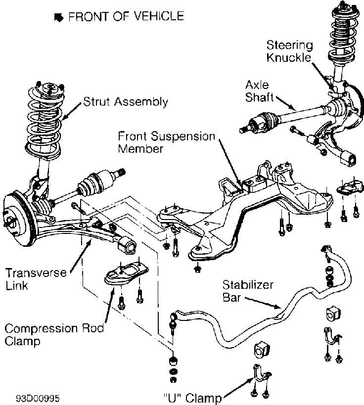
Fig. 1: Exploded View Of Front Suspension Courtesy of Nissan Motor Co., U.S.A.
ADJUSTMENTS & INSPECTION
WHEEL ALIGNMENT SPECIFICATIONS & PROCEDURES
NOTE: See WHEEL ALIGNMENT SPECIFICATIONS & PROCEDURES article in the WHEEL ALIGNMENT section.
WHEEL BEARING
Wheel bearing is not adjustable. To check wheel bearing, loosen axle nut and retighten to specification. See TORQUE SPECIFICATIONS table at the end of this article. Using a dial indicator, measure axial end play at wheel hub. Maximum axial end play is .002" (.05 mm). If reading exceeds specification, replace wheel bearing assembly.
BALL JOINT CHECKING
1) Jack up front of vehicle and support with stands. Check ball joint for grease leakage and dust cover for cracks or damage. Check ball joint end play.
2) Attach dial indicator to transverse link with indicator tip against lower edge of brake caliper. Ensure front wheels are in straight-ahead position. Place a pry bar between transverse link and wheel.
3) With brake pedal depressed, raise and release pry bar. Observe dial indicator. There should be zero vertical end play. If reading exceeds specification, replace transverse link. Ball joint cannot be replaced separately.
4) Remove ball joint assembly and place in a vise. See BALL JOINT under REMOVAL & INSTALLATION. Rotate ball joint at least 10 revolutions prior to checking with pull scale. This will ensure ball joint is properly seated.
5) Attach a pull scale at cotter pin hole of ball stud and check torque. See Fig. 2. On NX and Sentra, reading should be 1.8-13.0 lbs. (.8-5.9 kg). If reading is not within specification, replace ball joint.
6) Install ball joint stud nut. Using an INCH-lb. torque wrench, measure amount of torque required to turn ball joint stud. See Fig. 2. On all models, reading should be 4.3-30.4 INCH lbs. (0.49-3.43 N.m). If reading is not within specification, replace ball joint.
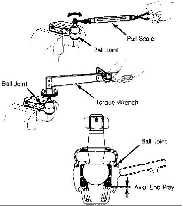
Fig. 2: Checking Ball Joint Courtesy of Nissan Motor Co., U.S.A.
REMOVAL & INSTALLATION
COIL SPRING & STRUT ASSEMBLY
Removal
1) Raise and support vehicle. Remove wheel. Disconnect brake line from strut. Support lower control arm. Mark position of strut to steering knuckle for installation reference. Remove strut-to-steering knuckle nuts and bolts. Remove nuts attaching upper strut to body. DO NOT remove piston rod lock nut.
2) Remove strut and coil spring assembly from vehicle. Secure strut assembly in a soft-jawed vise. Slightly loosen piston rod lock nut. Compress spring with spring compressor and remove piston rod lock nut. Remove spring from strut assembly.
Inspection
Check strut for smooth operation through a full stroke, both compression and extension. Check for oil leakage. Check piston for cracks, deformation or other damage.
Installation
1) Ensure flat spring surface is facing upward. Install spring onto strut assembly. To complete installation, reverse removal procedure.
2) Ensure arrow on spring seat is facing outside of vehicle. Tighten nuts and bolts to specification. See TORQUE SPECIFICATIONS table at the end of this article.
HUB & KNUCKLE ASSEMBLY
Removal & Installation
1) Raise and support vehicle. Remove wheel. Apply brakes and remove axle nut. Remove brake caliper and wire out of way. Remove tie rod end from steering knuckle. To prevent damage, wrap shop rags around axle shaft boots. Keep axle shaft straight at all times.
2) Separate axle shaft from hub by tapping on end of axle shaft with a plastic hammer. See Fig. 3. Mark position of strut to steering knuckle for installation reference. Remove strut-to-steering knuckle nuts and bolts. Separate lower ball joint from steering knuckle. Remove hub and knuckle assembly.
3) To install, reverse removal procedure. Tighten nuts and bolts to specification. See TORQUE SPECIFICATIONS table at the end of this article. Check wheel alignment. See appropriate WHEEL ALIGNMENT SPECIFICATIONS & PROCEDURES article in the WHEEL ALIGNMENT section.
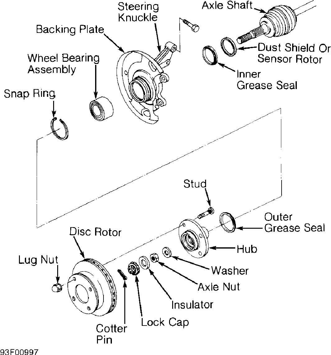
Fig. 3: Exp View Of Hub & Knuckle Assembly Courtesy of Nissan Motor Co., U.S.A.
TRANSVERSE LINK & BALL JOINT
Removal
1) Raise and support vehicle. Remove wheel. Remove hub and knuckle assembly. See HUB & KNUCKLE ASSEMBLY.
2) Disconnect stabilizer bar from transverse link. Remove compression rod clamp. On NX and Sentra, remove transverse link pivot bolt. On all models, remove transverse link and ball joint assembly.
Installation
1) Position transverse link and ball joint assembly. Install pivot bolt or nut. Ensure proper position of compression rod clamp and install. Reconnect stabilizer bar connecting rod to transverse link. DO NOT tighten transverse link nuts and bolts to specification at this time. Final tightening must be performed with vehicle on ground.
2) To complete installation, reverse removal procedure. Tighten nuts and bolts to specification. See TORQUE SPECIFICATIONS table at the end of this article. Place vehicle on ground. Bounce vehicle up and down several times. Tighten transverse link nuts and bolts to specification. See TORQUE SPECIFICATIONS table at the end of this article. Check wheel alignment. See appropriate WHEEL ALIGNMENT SPECIFICATIONS & PROCEDURES article in the WHEEL ALIGNMENT section.
STABILIZER BAR
Removal & Installation
1) Raise and support vehicle. Remove nut, washer and spacer retaining stabilizer bar to transverse link by holding upper nut while removing lower nut. See Fig. 4. Mark position of "U" clamps to ensure installation to original location. Remove "U" clamps retaining stabilizer bar to gusset. Remove stabilizer bar.
2) To install, reverse removal procedure. Ensure stabilizer connecting rod is positioned properly. See Fig. 4. Tighten nuts and bolts to specification with vehicle on ground. See TORQUE SPECIFICATIONS table at the end of this article.

Fig. 4: Installing Stabilizer Connecting Rod Courtesy of Nissan Motor Co., U.S.A.
WHEEL BEARING
NOTE: Replace wheel bearing assembly and seals if hub and steering knuckle are separated.
Removal
1) Raise and support vehicle. Remove hub and knuckle assembly. See HUB & KNUCKLE ASSEMBLY under REMOVAL & INSTALLATION. Place assembly in a soft-jawed vise. Drive hub and inner race from steering knuckle. See Fig. 5. Press inner race from hub.
2) Remove inner and outer grease seals from steering knuckle. Remove snap ring from steering knuckle. See Fig. 3. Press wheel bearing assembly from steering knuckle.

Fig. 5: Separating Hub & Steering Knuckle Courtesy of Nissan Motor Co., U.S.A.
Installation
1) Press new bearing assembly into steering knuckle. DO NOT press on inner race of bearing assembly. DO NOT apply grease to wheel bearing outer surface and steering knuckle mating surface. Install outer snap ring.
2) Install inner and outer grease seals. Press hub into steering knuckle. DO NOT apply more than 6600 lbs. (2994 kg) of pressure. To complete installation, reverse removal procedure. Tighten nuts and bolts to specification. See TORQUE SPECIFICATIONS table at the end of this article.
TORQUE SPECIFICATIONS
TORQUE SPECIFICATIONS TABLE
�������������������������������������������������������������������������������������������������������������������������������������������
Application Ft. Lbs. (N.m)
Axle Nut ......................................... 145-203 (196-275) Ball Joint Stud Nut .................................. 44-55 (59-74) Caliper Mounting Bolt ................................ 40-47 (54-64) Compression Rod Clamp Bolt ........................... 58-72 (78-98) Connecting Rod-To-Transverse Link Nut ................ 15-21 (20-29) Stabilizer Bar-To-Connecting Rod Nut ................. 34-38 (46-52) Stabilizer Bar "U" Clamp Bolt ........................ 23-31 (31-42) Strut Piston Rod Nut ................................. 46-53 (62-72) Strut-To-Body Nut .................................... 18-21 (25-29) Strut-To-Steering Knuckle Nut ...................... 84-98 (114-133) Tie Rod Lock Nut ..................................... 27-34 (37-46) Tie Rod Stud Nut ..................................... 21-29 (29-39) Transverse Link-To-Suspension Member Nut ........... 76-91 (103-123) Wheel Lug Nut ....................................... 72-87 (98-118)
�������������������������������������������������������������������������������������������������������������������������������������������