
�SUSPENSION -REAR
�1993 Nissan Sentra
1993 SUSPENSION Nissan Rear
NX & Sentra
DESCRIPTION
Vehicles use a MacPherson strut type rear suspension system. Upper end of strut is bolted to upper body of vehicle. Lower end of strut is bolted to rear knuckle. Rear suspension uses front and rear parallel links which attach to a crossmember and rear knuckle. A radius rod is attached to rear knuckle and vehicle body. See Fig. 1.
A stabilizer bar is attached to a connecting rod at lower end of strut. Brackets attach stabilizer bar to body of vehicle. An eccentric bolt is located on each inner rear parallel link for adjusting rear toe.
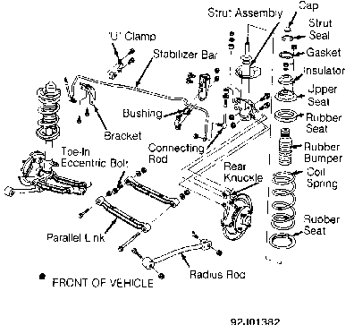
Fig. 1: Exploded View Of Rear Suspension Courtesy of Nissan Motor Co., U.S.A.
ADJUSTMENTS & INSPECTION
CAUTION: DO NOT place jack under parallel links or radius rods when raising vehicle.
WHEEL ALIGNMENT SPECIFICATIONS & PROCEDURES
NOTE: See WHEEL ALIGNMENT SPECIFICATIONS & PROCEDURES article in the WHEEL ALIGNMENT section.
WHEEL BEARING
Wheel bearing is not adjustable. Loosen wheel bearing lock nut and tighten to specification. See TORQUE SPECIFICATIONS table at the end of this article. Using a dial indicator, check axial end play. Axial end play must be less than .002" (.05 mm). If axial end play is not within specification or wheel bearing does not rotate smoothly, replace wheel bearing assembly. See WHEEL BEARING under REMOVAL & INSTALLATION.
REMOVAL & INSTALLATION
CAUTION: DO NOT place jack under parallel links or radius rods when raising vehicle.
COIL SPRING & STRUT ASSEMBLY
Removal
1) Raise and support vehicle. Remove wheel. Place a jack under hub assembly to prevent suspension from dropping during strut removal. DO NOT raise up on hub assembly with jack.
2) Remove 3 upper strut-to-body mounting nuts. Remove stabilizer bar connecting rod nuts from strut lower end. Remove 2 lower strut-to-rear knuckle retaining nuts and bolts. Remove coil spring and strut assembly. Place coil spring and strut assembly in a soft-jawed vise. Loosen piston rod lock nut. DO NOT remove piston rod lock nut.
3) Install a coil spring compressor and compress spring just enough to rotate strut mounting insulator by hand. Remove piston rod lock nut. Remove strut mounting insulator, upper spring seat and coil spring. See Fig. 1.
Inspection
Check strut for smooth operation through a full stroke, both compression and extension. Check for oil leakage. Check piston for cracks, deformation or other damage.
Installation
1) Position coil spring on strut assembly with flat side of coil spring upward. Ensure bottom side of coil spring is seated properly in lower spring seat on strut. Install upper spring seat and strut mounting insulator.
2) When installing spring seat, ensure arrow on spring seat points toward outside of vehicle and is in line with strut-torear knuckle slot on lower end of strut. See Fig. 2. To complete installation, reverse removal procedure. Tighten nuts and bolts to specification with vehicle on ground. See TORQUE SPECIFICATIONS table at the end of this article. Check wheel alignment. See WHEEL ALIGNMENT SPECIFICATIONS & PROCEDURES article in the WHEEL ALIGNMENT section.
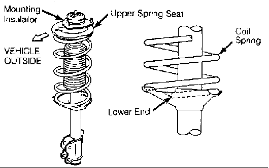
Fig. 2: Positioning Coil Spring & Mounting Insulator Courtesy of Nissan Motor Co., U.S.A.
PARALLEL LINK
Removal
Raise and support vehicle. Place marks on toe-in eccentric adjusting bolts and crossmember for reassembly reference. See Fig. 3. Mark front and rear parallel link for reassembly reference. Remove nuts and bolts retaining parallel link to crossmember. Remove nuts and bolts retaining parallel link to rear knuckle. Remove parallel link.
Installation
To install, reverse removal procedure. Tighten nuts and bolts to specification with vehicle on ground. See TORQUE SPECIFICATIONS table at the end of this article. Check wheel alignment. See WHEEL ALIGNMENT SPECIFICATIONS & PROCEDURES article in the WHEEL ALIGNMENT section.
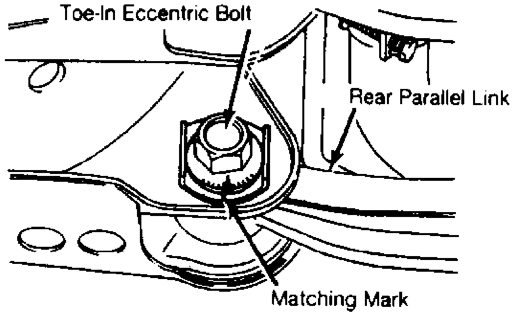
Fig. 3: Marking Toe-In Eccentric Adjusting Bolt Courtesy of Nissan Motor Co., U.S.A.
RADIUS ROD
Removal
Raise and support vehicle. Mark position of radius rod in reference to front and rear of vehicle. See Fig. 1. Remove nut and bolt retaining radius rod to rear knuckle. Remove nut and bolt retaining radius rod to body of vehicle. Remove radius rod.
Installation
To install, reverse removal procedure. Ensure radius rod is installed properly. Tighten nuts and bolts to specification with vehicle on ground. See TORQUE SPECIFICATIONS table at the end of this article.
REAR KNUCKLE
Removal
1) Remove hub and wheel bearing assembly. See WHEEL BEARING under REMOVAL & INSTALLATION. On vehicles with disc brakes, remove brake caliper and wire out of way. On vehicles with drum brakes, disconnect brake line at wheel cylinder. Disconnect parking brake. Remove backing plate assembly.
2) On all models, remove 2 lower strut-to-rear knuckle retaining nuts and bolts. Remove nuts retaining radius rod to rear knuckle. Remove nuts and bolts retaining front and rear parallel links to rear knuckle. See Fig. 1. Use care not to drop rear knuckle. Remove rear knuckle.
Installation
To install, reverse removal procedure. Tighten nuts and bolts to specification with vehicle on ground. See TORQUE SPECIFICATIONS table at the end of this article.
STABILIZER BAR
Removal & Installation
Remove stabilizer bar-to-strut connecting rod nuts. Remove link bolts, washers, insulators and nuts. Remove stabilizer bar-tobody bracket nuts, bolts and "U" clamps. See Fig. 1. Remove stabilizer bar. To install, reverse removal procedure. Tighten nuts and bolts to specification with vehicle on ground. See TORQUE SPECIFICATIONS table at the end of this article.
WHEEL BEARING
CAUTION: DO NOT install used wheel bearing hub assembly if removed.
Removal
1) Raise and support vehicle. Remove wheel. On vehicles with disc brakes, remove dust cover and cotter pin. Apply brakes and loosen wheel bearing lock nut. Remove brake caliper and wire out of way. Remove disc rotor. Remove wheel bearing lock nut and washer. Remove hub and wheel bearing assembly.
2) On vehicles with drum brakes, remove dust cap and cotter pin. Apply brakes and loosen wheel bearing lock nut. Remove brake drum. Remove wheel bearing lock nut and washer. Remove hub and wheel bearing assembly.
Installation
To install, reverse removal procedure. Tighten wheel bearing lock nut to specification. Tighten nuts and bolts to specification. See TORQUE SPECIFICATIONS table at the end of this article.
TORQUE SPECIFICATIONS
TORQUE SPECIFICATIONS TABLE
�������������������������������������������������������������������������������������������������������������
Application Ft. Lbs. (N.m)
Backing Plate Bolt .................... 28-38 (38-52) Brake Caliper Torque Member Bolt ...... 40-47 (54-64) Connecting Rod-To-Strut Nut ........... 14-22 (20-29) Parallel Link-To-Crossmember Bolt .... 72-87 (98-118) Parallel Link-To-Rear Knuckle Nut .... 72-87 (98-118) Radius Rod-To-Body Bolt .............. 72-87 (98-118) Radius Rod-To-Rear Knuckle Nut ....... 72-87 (98-118)
Stabilizer Bar-To-Connecting Rod Nut .. 34-38 (46-52) Stabilizer Bar-To-Frame Bracket Nut ... 23-31 (31-42) Strut Piston Rod Lock Nut ............. 46-53 (62-72) Strut-To-Body Nut ..................... 18-22 (25-29) Strut-To-Knuckle Nut ................. 72-98 (98-133) Toe-In Eccentric Bolt ................ 72-87 (98-118) Wheel Bearing Nut ................. 137-188 (186-255) Wheel Lug Nut ........................ 72-87 (98-118)
�������������������������������������������������������������������������������������������������������������