
�G -TESTS W/CODES -1.6L
�1993 Nissan Sentra
1993 ENGINE PERFORMANCE Nissan Self-Diagnostics
NX & Sentra 1.6L
INTRODUCTION
If no faults were found while performing F - BASIC TESTING proceed with self-diagnostics. If no fault codes or only pass codes are present after entering self-diagnostics, proceed to appropriate H - TESTS W/O CODES article for diagnosis by symptom (i.e., ROUGH IDLE, NO START, etc.).
NOTE: Trouble codes are also called Diagnostic Trouble Codes (DTC).
SELF-DIAGNOSTIC SYSTEM
Self-diagnostic system is used for diagnosing malfunctions of Electronic Concentrated Control System (ECCS) sensors and actuators. Engine Control Module (ECM) has a number of available diagnostic modes within computer.
NX & Sentra have 2 modes with subdivisions. Before selecting any mode of self-diagnostics, always perform procedures described in F - BASIC TESTING article. Doing so prevents wasted time and false diagnostic results.
Consult Tester
In addition to self-diagnostic capability, all models are equipped with a diagnostic connector for use with Nissan Consult Tester (J-38465). Connector is located behind fuse box cover on NX and
| Sentra. | |
|---|---|
| NOTE: | When performing F - BASIC TESTING be careful not to erase any diagnostic information stored in ECM memory. |
| Hard Failures Hard failures cause CHECK ENGINE light (if equipped) to | |
illuminate and remain on until problem is repaired. If light comes on and remains on (light may flash) during vehicle operation, cause of malfunction must be determined using diagnostic (code) charts. If a sensor fails, ECM will use a substitute value in its calculations to continue engine operation. In this condition (fail-safe mode), the vehicle runs but driveability will not be optimum and engine speed is restricted (2000-3000 RPM depending on model).
Intermittent Failures
Intermittent failures may cause CHECK ENGINE light (if equipped) to flicker or illuminate and go out after intermittent fault goes away. However, corresponding trouble code will be retained in ECM memory. If related fault does not reoccur within 50 ignition cycles, related trouble code will be erased from ECM memory. Intermittent failures may be caused by sensor, connector or wiring problems. See INTERMITTENTS in H - TEST W/O CODES article.
NOTE: Follow diagnostic routine when testing engine control
systems. See DIAGNOSTIC ROUTINE table for correct order of
procedure.
DIAGNOSTIC ROUTINE TABLE
�����������������������������������������������������������������������������������������������������������������������
Procedure Order
Basic Diagnostic Procedures .......................... 1st Entering Diagnostics ................................. 2nd Retrieving Trouble Codes ............................. 3rd Symptoms (1) ......................................... 4th Intermittents (1) .................................... 5th
(1) - See H - TESTS W/O CODES article.
�����������������������������������������������������������������������������������������������������������������������
CHECK ENGINE LIGHT
All models except Pickup 2.4L (Federal) are equipped with a CHECK ENGINE light. As a bulb check, light will illuminate when ignition is on and engine is not running. CHECK ENGINE light will also illuminate when an engine control system fault has been detected. Not all trouble codes activate CHECK ENGINE light.
DIAGNOSTIC MODES
Self-diagnostic system can detect engine control system malfunctions and store related trouble codes. Trouble codes, including intermittent codes, are stored in ECM memory and are available for retrieval unless codes have been cleared.
Self-diagnostic system uses single or dual Light Emitting Diodes (LED), located on ECM. See ECM LOCATION table. For system application, see SELF-DIAGNOSTIC SYSTEM table.
ECM LOCATIONS TABLE
���������������������������������������������������������������������������������������������������������������������������
Application Location
NX & Sentra .......................... Behind Center Console
���������������������������������������������������������������������������������������������������������������������������
SELF-DIAGNOSTIC SYSTEM TABLE
���������������������������������������������������������������������������������������������������������������������������
| CHECK ENGINE | LED | ||||
|---|---|---|---|---|---|
| Application | Light | Colors (No.) | |||
| NX | ............... | Calif. & Fed. | ................. | Red (1) | |
| Sentra | ........... | Calif. & Fed. | ................. | Red (1) | |
���������������������������������������������������������������������������������������������������������������������������
SINGLE LED SYSTEM
Self-diagnostic system will operate in 2 modes which are manually selected using a screwdriver through access port on ECM. With ignition switch in ON position and engine not running, use screwdriver to turn switch fully clockwise. Wait at least 2 seconds. Turn screwdriver fully counterclockwise. Inspection light will begin to flash.
NOTE: Modes cannot be switched while engine is running. When
ignition switch is turned to OFF position while in Mode II,
ECM switches to Mode I.
Mode I (Bulb Check)
Engine is not running in this mode. Turn ignition switch to ON position. Red LED on ECM and CHECK ENGINE light (if equipped) should be lit. If lights do not illuminate, check and replace bulbs as
necessary.
Mode I (Malfunction Warning)
This is normal vehicle operating mode and engine must be running. On California vehicles, if a malfunction occurs, Red LED and CHECK ENGINE light (if equipped) will illuminate, indicating an engine control system malfunction has occurred and a code has been stored. On Federal vehicles, codes are stored and only Red LED will illuminate when ECM’s Central Processing Unit (CPU) malfunctions.
Mode II (Self-Diagnostics)
When Mode II is accessed (engine not running), codes stored in ECM memory will be flashed by CHECK ENGINE light (if equipped) and Red LED on side of ECM.
Long flashes (.6 second) indicate first digit of code. Short flashes (.3 second) indicates second digit of code. For example: one long flash followed by 2 short flashes indicate a Code 12. See Fig. 1.
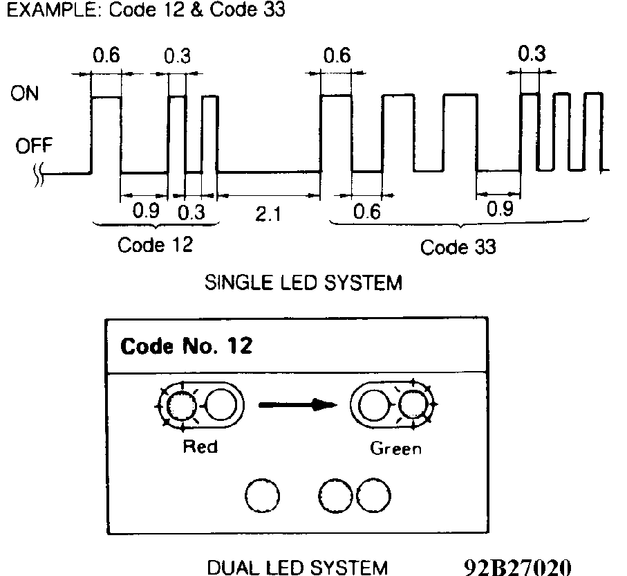
Fig. 1: Trouble Code Display Courtesy of Nissan Motor Co., U.S.A.
Mode II (Exhaust Gas Monitor) In Mode II (engine running), Red LED and CHECK ENGINE light
are used to monitor air/fuel mixture feedback control. Vehicle must be in closed loop for Mode II results to be valid.
In open loop, Red LED remains either on or off. In closed loop, Red LED indicates if system is running rich (light off), lean (light on) or at ideal air/fuel ratio (blinking synchronized with CHECK ENGINE light).
If 2 oxygen sensors are used (left and right side), left side is monitored first. To switch to right side, start engine and allow to idle. Turn screwdriver fully clockwise. Wait at least 2 seconds. Turn screwdriver fully counterclockwise. Inspection light will begin to flash. This is Mode II.
DUAL LED SYSTEM
Self-diagnostic system can be operated in any of 5 modes. Modes are manually changed using screwdriver through access port on ECM. With screwdriver turned fully clockwise, inspection lights will begin to flash. Count number of flashes. First flash is Mode I, second flash is Mode II, etc. When desired mode has been indicated, turn screwdriver fully counterclockwise. In different modes, Red LED and Green LED perform different functions.
Mode I (Exhaust Gas Monitor)
This is normal vehicle operating mode. Green LED will indicate loop status. If Green LED is not blinking, vehicle is in open loop or a fault exists with oxygen sensor or sensor circuit. If Green LED is blinking, vehicle is in closed loop. If a malfunction occurs in Mode I, Red LED and CHECK ENGINE light (if equipped) will illuminate, indicating an engine control system malfunction has occurred.
Mode II (Mixture Ratio Feedback Monitor)
In Mode II, both Red LED and Green LED are used to monitor air/fuel mixture feedback control. Green LED will function as in Mode
I. In open loop, Red LED and Green LED will remain on or off. For results to be valid, vehicle must be in closed loop. In closed loop, Red LED will indicate if system is running rich (light off), lean (light on) or at ideal air/fuel ratio (blinking synchronized with Green LED).
Mode III (Self-Diagnostics)
When Mode III is accessed, codes stored in ECM memory will be flashed by Green LED and Red LED on side of ECM. Green LED will flash first digit of code, while Red LED will flash second digit of code. For example: 3 flashes of Green LED followed by 5 flashes of Red LED indicate a Code 35.
Mode IV (Switch Check)
This mode is used for checking engine control system’s switch status. When idle switch or starter switch is activated, Red LED will come on and go off as status changes. For vehicle speed sensor status, Green LED will remain off when vehicle speed is less than 12 MPH and come on when vehicle speed is greater than 12 MPH.
Mode V (Test Mode)
Mode V represents a real-time diagnostic test of crank angle sensor, ignition signal, airflow output signal and fuel pump (Maxima). This mode is accessed for an in-bay running test of vehicle. Red and Green LEDs must be monitored carefully during this test, with special attention paid to number of flashes before each pause.
Malfunction code will be displayed only once and will not be stored in memory. If Red LED blinks on and off evenly, a fault exists in crank angle sensor. If Green LED flashes twice before a pause, a fault exists in airflow meter. If Red LED blinks 3 times before a
pause, a fault exists in fuel pump circuit. If Green LED blinks 4 times before a pause, a fault exists in ignition signal.
ENTERING SELF-DIAGNOSTICS
Single LED System
1) Self-diagnostic system normal operational mode is Mode I. With ignition switch in ON position and engine not running, insert screwdriver through access port on ECM.
2) Turn screwdriver fully clockwise. Wait at least 2 seconds. Turn screwdriver fully counterclockwise. Inspection light will begin to flash. This is Mode II.
NOTE: Modes cannot be switched when engine is running. When
ignition switch is turned to OFF position, ECM will switch
to Mode I.
Dual LED System
1) Turn ignition switch to ON position. Use a screwdriver to turn ECM diagnostic mode selector fully clockwise.
2) Wait for inspection lights to begin flashing. At this time, inspection lights will flash mode options (i.e., one flash for Mode I, 2 flashes for Mode II, etc.). As soon as inspection light flashes desired mode number (3 flashes for self-diagnostic mode), turn mode selector off (fully counterclockwise).
3) If mode selector is kept in ON position (fully clockwise), mode selections will continuously cycle. This cycling will not erase memory.
RETRIEVING CODES
Single LED System
When Mode II is accessed (engine not running), codes stored in ECM memory will be flashed by CHECK ENGINE light and Red LED on side of ECM. Long flashes (.6 second) indicate first digit of code. Short flashes (.3 second) indicate second digit of code. For example: 3 long flashes followed by 5 flashes of Red LED (or CHECK ENGINE light) indicate a Code 35.
Dual LED System
Trouble codes are read using Red LED and Green LED inspection lights on side of ECM. After selecting Mode III, trouble codes corresponding to mode will start flashing. Trouble codes are indicated by number of flashes from ECM Red LED and Green LED inspection lights. Count number of flashes. Red LED indicates first digit of code, and Green LED indicates second digit of code. For example, 3 flashes of Red LED followed by 2 flashes of Green LED indicate Code 32.
TROUBLE CODE DEFINITION
NOTE: Not all trouble codes will activate CHECK ENGINE light.
TROUBLE CODE IDENTIFICATION CHART (NX & SENTRA)
���������������������������������������������������������������������������������������������������������������
Code System/Circuit Affected
11 ................................ Crank Angle Sensor 12 ............................... Mass Airflow Sensor 13 ............... Engine (Coolant) Temperature Sensor 14 .............................. Vehicle Speed Sensor 21 ............................. No Ignition Reference 31 ....................... Engine Control Module (ECM) 32 ............................... EGR Sensor (Calif.)
33 ..................................... Oxygen Sensor 34 .................. Knock (Detonation) Sensor (2.0L) 35 ......................... EGR Temp. Sensor (Calif.) 43 .......................... Throttle Position Sensor 45 ............................ Injector Leak (Calif.) 55 ........................... No Malfunction Recorded
���������������������������������������������������������������������������������������������������������������
CLEARING CODES
NOTE: Ensure all diagnostic codes are retrieved from ECM memory before disconnecting battery or erasing stored memory.
Memory Erase (Single LED System)
Stored memory will be erased if battery is disconnected for 24 hours or diagnostic mode is switched from Mode II to Mode I (modes cannot be switched with engine running). To switch from Mode II to Mode I while in Mode II with engine off, turn diagnostic mode selector fully clockwise. Wait for at least 2 seconds, and turn mode selector fully counterclockwise.
Memory Erase (Dual LED System)
Stored memory will be erased if battery is disconnected for 24 hours or Mode IV is selected after Mode III has been accessed. However, if mode selector switch is turned fully clockwise, diagnostic modes will continue to cycle until a mode is selected. This cycling does not erase stored memory.
FINAL CHECK
Final Check For All CIRCUIT TESTS
Unless otherwise instructed in code inspection, perform following final check after each repair is completed.
- *
- Erase diagnostic test Mode II (self-diagnostic results) memory. See CLEARING CODES under SELF-DIAGNOSTIC SYSTEM.
- *
- Ensure Code 55 (no malfunction) is displayed in self-diagnostic mode.
- *
- Perform a test drive.
- *
- Perform diagnostic test Mode II (self-diagnostic results) again.
If results are okay, inspection is complete. If results are not okay, ensure ECM pin terminals and ECM harness connector are not damaged.
SUMMARY
If no hard fault codes (or only pass codes) are present, driveability symptoms exist or intermittent codes exist, proceed to H - TESTS W/O CODES article for diagnosis by symptom (i.e., ROUGH IDLE, NO START, etc.) or intermittent diagnostic procedures.
DIAGNOSTIC TROUBLE CODE (DTC) TESTS
NOTE: Procedures using Nissan Consult Tester (J-38465) are
provided when available. If circuit test is being performed
without Consult tester, use alternate test procedure.
ECM HARNESS CONNECTOR
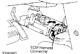
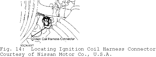
Fig. 2: Locating ECM Harness Connector Courtesy of Nissan Motor Co., U.S.A.
Fig. 3: ECM Harness Connector Terminal ID (Harness Side Of Connector) Courtesy of Nissan Motor Co., U.S.A.
DTC 11, CRANKSHAFT POSITION (CKP) SENSOR
1) Check Power Supply
Turn ignition off. Disconnect CKP sensor wiring harness connector. Turn ignition on. Measure voltage between CKP sensor harness connector terminal "b" and ground. See Fig. 4. If battery voltage is present, go to next step. If battery voltage is not present, check open or short circuit between CKP sensor and ECM and/or between CKP sensor and ECCS relay.
2) Check Input Signal Circuit
Turn ignition off. Disconnect ECM harness connector. See Fig. 2. Check continuity between CKP sensor harness connector terminal "d" (Blue wire) and ECM harness connector terminals No. 22 and 30 (180-degree signal). See Figs. 3 and 5. Check continuity between CKP sensor harness connector terminal "c" (Yellow wire) and ECM terminals No. 31 and 40 (one-degree signal). If continuity is present, go to next step. In continuity is not present, repair wiring harness or connectors as necessary.
3) Check Component
Inspect CKP sensor. See I - SYS/COMP TESTS article. If CKP sensor is defective, replace as necessary and perform FINAL CHECK in this article. If CKP sensor is okay, check ECM wiring harness connector and repair or replace as necessary.
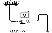
Fig. 4: DTC 11, Checking Power Supply Courtesy of Nissan Motor Co., U.S.A.
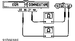
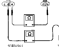
Fig. 5: DTC 11, Checking Input Signal Circuit Courtesy of Nissan Motor Co., U.S.A.
DTC 12, MASS AIRFLOW (MAF) SENSOR
1) Check Power Supply
Turn ignition off. Disconnect MAF sensor harness connector. See Fig. 6. Turn ignition on. Measure voltage between MAF sensor harness connector terminal "b" (Orange/Blue wire) and ground. See Fig. 7. If battery voltage is present, go to next step. If battery voltage is not present, repair harness or connectors as necessary.
2) Check Ground Circuit
Turn ignition off. Disconnect ECM harness connector. Check continuity between MAF sensor connector terminal "c" (White wire) and ECM terminal No. 17. See Figs. 3 and 8. If continuity is present, go to next step. If continuity is not present, repair harness or connectors as necessary.
3) Check Input Signal Circuit
Check continuity between MAF sensor connector terminal "d" (Orange wire) and ECM harness connector terminal No. 16. See Figs. 3 and 9. If continuity is not present, repair harness or connectors as necessary. If continuity is present, go to next step.
4) Check MAF Sensor
Inspect MAF sensor. See I - SYS/COMP TESTS article. Replace MAF sensor if necessary and perform FINAL CHECK in this article. If MAF sensor is okay, check ECM wiring harness connector and repair or replace as necessary.
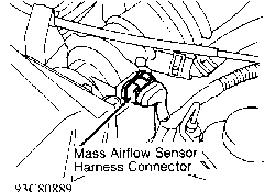
Fig. 6: Locating MAF Sensor Harness Connector Courtesy of Nissan Motor Co., U.S.A.
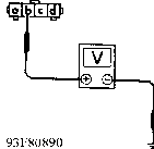
Fig. 7: DTC 12, Checking Power Supply Courtesy of Nissan Motor Co., U.S.A.
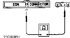
Fig. 8: DTC 12, Checking Ground Circuit Courtesy of Nissan Motor Co., U.S.A.
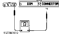
Fig. 9: DTC 12, Checking Input Signal Circuit Courtesy of Nissan Motor Co., U.S.A.
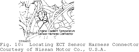
DTC 13, ENGINE COOLANT TEMPERATURE (ECT) SENSOR
1) Check Power Supply
Turn ignition off. Disconnect ECT sensor harness connector. See Fig. 10. Turn ignition on. Measure voltage between ECT sensor harness connector terminal "b" (Gray wire) and ground. See Fig. 11. If voltage is about 5 volts, go to next step. If voltage is not as specified, repair harness or connectors as necessary.
2) Check Ground Circuit
Turn ignition off. Check continuity between terminal "a" (Blue/Orange wire) and engine ground. See Fig. 12. If continuity is present, go to next step. If continuity is not present, repair harness or connectors as necessary.
3) Check Component
Inspect ECT sensor. See I - SYS/COMP TESTS article. Replace ECT sensor if necessary and perform FINAL CHECK in this article. If ECT sensor is okay, check ECM pin terminals and wiring harness connector and repair as necessary.
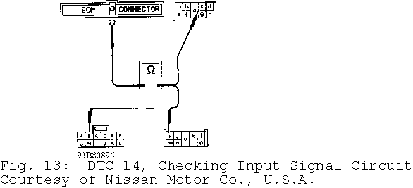
DTC 14, VEHICLE SPEED SENSOR (VSS)
1) Check Speedometer Operation
VSS is built into speedometer. Ensure speedometer operates properly. If speedometer operates properly, go to next step. If speedometer does not operate properly, remove VSS from transaxle. Set voltmeter on AC scale. Connect voltmeter to VSS connector terminals. Turn VSS pinion gear. Voltage should be approximately 0.5 volt. If voltage is not correct, replace vehicle speed sensor. If voltage is correct, go to next step.
2) Check Input Signal Circuit
Turn ignition off. Disconnect ECM and combination meter wiring harness connector. Check harness continuity between ECM terminal No. 32 and following combination meter terminal. See Fig. 13.
- *
- Terminal "B" (Yellow/Green wire) on models with digital instruments
- *
- Terminal "c" (Yellow/Green wire) on models with tachometer.
- *
- Terminal "i" (Yellow/Green wire) on models without tachometer.
If continuity is present, check ECM pin terminals and connector and repair as necessary. If continuity is not present, repair wiring harness or connectors as necessary and perform FINAL CHECK in this article.
DTC 21, IGNITION SIGNAL
1) Check Power Supply
If vehicle does not start, go to step 5). If vehicle starts, turn ignition off. Disconnect ignition coil harness connector. See Fig. 14. Turn ignition on. Measure voltage between ignition coil harness connector terminal "a" (Gray wire) and ground. See Fig. 15. If battery voltage is not present check wiring harness and connectors between ignition coil and ignition switch for open or short circuit. If battery voltage is present, go to next step.
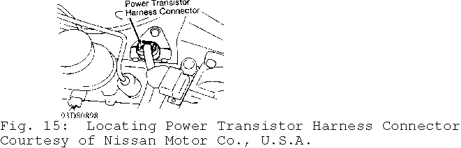
2) Check Ground Circuit
Turn ignition off. Disconnect power transistor wiring harness connector. See Fig. 15. Check continuity between engine ground and ignition coil connector terminal "d" (Black/Red wire). Check continuity between engine ground and power transistor connector terminals "b" (Black wire) and "e" (Green/Yellow wire). See Fig. 18. If continuity is present, go to next step. If continuity is not present, repair wiring harness or connectors as necessary and perform FINAL CHECK in this article.
3) Check Output Signal Circuit
Turn engine off. Leave power transistor disconnected. Disconnect ECM harness connector. See Fig. 2. Check continuity between terminal "c" (White wire) of power transistor wiring harness connector and terminal No. "1" of ECM wiring harness connector. See Figs. 3 and
19. If continuity is present, go to next step. If continuity is not
present, repair harness or connectors as necessary.
4) Check Components
Inspect ignition coil and power transistor. See appropriate I - SYS/COMP TESTS article. Replace ignition coil and/or power transistor if necessary and perform FINAL CHECK in this article. If ignition coil and power transistor are okay, repair ECM pin terminal(s) and/or wiring harness connector.
5) Check Input Signal
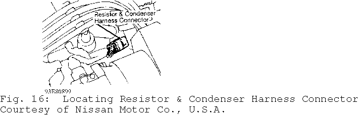
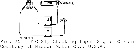
Perform this step if vehicle does not start. Ensure ignition is off. Disconnect ignition coil wiring harness connector. Leave resistor and condenser connected. See Fig. 16. Check continuity between ignition coil harness connector "b" and resistor/condenser connector terminal "f". See Fig. 20. Check continuity between ECM terminal No. "3" and resistor/condenser connector terminal "g". If
continuity is present, go to step 4). If continuity is not present, replace resistor and condenser.
DTC 31, ECM
Turn ignition on. Erase self-diagnostic test Mode II memory. Perform self-diagnostic test Mode II. If ECM displays DTC 31 again, replace ECM.
DTC 32, EGR FUNCTION
1) Check Vacuum Source To EGR Valve
Start engine and warm to operating temperature. Disconnect hose from EGR valve and check vacuum. Vacuum should not be present. Raise engine speed to about 2000 RPM and check vacuum. Vacuum should be present. If vacuum is not as specified, go to next step. If vacuum is as specified, inspect EGR valve and EGRC-BPT valve. See appropriate I - SYS/COMP TESTS article. Repair or replace as necessary and perform FINAL CHECK in this article.
2) Check Control Function
Start engine. Connect voltmeter between ECM terminal No. 105 and ground. See Figs. 3 and 22. At 2000 RPM, battery voltage should be present. At 4000 RPM, .6-.8 volt should be present. If voltage is not as specified, go to next step. If voltage is as specified, inspect vacuum hose for clogging, cracks or bad connection. Repair vacuum hose as necessary.
3) Check Output Signal Circuit
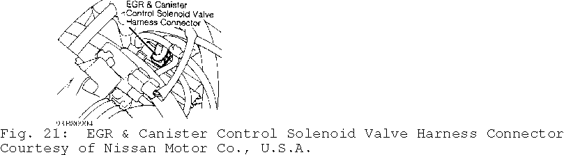
Turn engine off. Leave ECM disconnected. Disconnect EGR and canister control solenoid valve wiring harness connector. See Fig. 21. Check continuity between ECM terminal No. 105 (Red/Blue wire) and ground. See Figs. 3 and 23. Check continuity between EGR and canister control solenoid valve harness connector terminal "a" (Red/Blue wire) and ground. See Fig. 23. If continuity is present, repair wiring harness or connectors as necessary. If continuity is not present, go to next step.
4) Check Component
Measure resistance of EGR temperature sensor. Inspect EGR and canister control solenoid valve. See I - SYS/COMP TESTS article. Replace EGR and canister control solenoid valve and/or EGR temperature sensor if necessary and perform FINAL CHECK in this article. If components are okay, repair ECM pin terminals and/or connector terminals.
5) Check Component Using Consult Tester (J-38465)
Turn ignition off and connect Consult tester. Connect ECM harness connector and EGR and canister control solenoid valve harness connector. Turn ignition on. Perform EGRC SOL/V CIRCUIT in FUNCTION TEST mode. Turn EGR and canister control solenoid valve on and off using Consult tester in ACTIVE TEST mode. Replace EGR and canister control solenoid valve if operating sounds are not heard. Perform FINAL CHECK in this article.
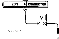
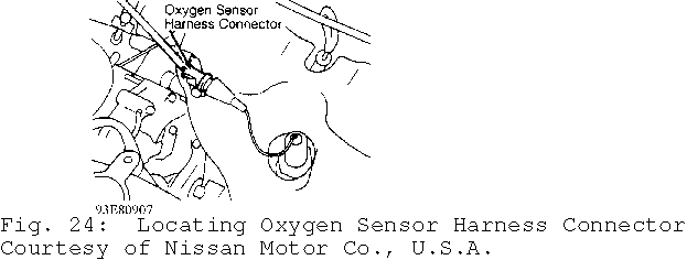
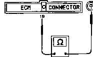
DTC 33, OXYGEN SENSOR
1) Check System Function
During self-diagnostic test Mode II, Red LED on ECM and MIL on instrument panel should blink 5 times within 10 seconds when engine speed is about 2000 RPM. If lights are as specified, testing is complete. If lights are not as specified, go to next step.
2) Check Input Signal Circuit
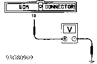
Turn ignition off. Disconnect oxygen sensor wiring harness connector. See Fig. 24. Disconnect ECM. See Fig. 2. Check continuity between oxygen sensor wiring harness connector terminal and ECM connector terminal No. 19. See Figs. 3 and 25. If continuity is present, replace oxygen sensor and perform FINAL CHECK in this article. If continuity is not present, repair harness or connectors as necessary.
3) Check Voltage
Turn ignition off. Reconnect oxygen sensor and ECM wiring harness connector. Start engine. Measure voltage between ECM terminal No. 19 and ground. See Figs. 3 and 26. Raise engine speed to about 2000 RPM. At 2000 RPM, voltage should fluctuate. If voltage remains fixed at 0.3 volts, replace oxygen sensor and perform FINAL CHECK in this article. If voltage fluctuates, repair ECM pin terminals and/or connector terminals.
4) Check Voltage Using Consult Tester (J-38465)
Turn ignition off. Connect Consult tester, oxygen sensor harness connector and ECM harness connector. Select DATA MONITOR mode with Consult tester. Raise engine speed to about 2000 RPM. Touch RECORD on Consult tester. Check O2 SEN voltage. If voltage remains fixed at 0.3 volts, replace oxygen sensor and perform FINAL CHECK in this article. If voltage fluctuates, repair ECM pin terminals and/or connector terminals.
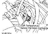
DTC 35, EGR TEMPERATURE SENSOR (CALIF.)
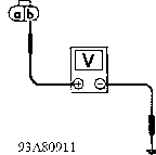
1) Check Power Supply
Turn ignition off. Disconnect EGR temperature sensor wiring harness connector. See Fig. 27. Turn ignition on. Measure voltage between EGR temperature sensor connector terminal "b" (Blue/Red wire) and ground. See Fig. 28. If voltage is about 4.5 volts, go to next step. If voltage is not about 4.5 volts, repair harness or connectors as necessary.
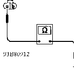
2) Check Ground Circuit
Turn ignition off. Check continuity between EGR temperature sensor connector terminal "a" (Gray wire) and engine ground. See Fig. 29. If continuity is present, go to next step. If continuity is not present, repair harness or connectors as necessary.
3) Check Component
Inspect EGR temperature sensor. See I - SYS/COMP TESTS article. Replace EGR temperature sensor if necessary and perform FINAL CHECK in this article. If EGR sensor is okay, repair ECM pin terminals or wiring harness connector.
DTC 43, THROTTLE POSITION (TP) SENSOR
1) Check Power Supply
Turn ignition off. Disconnect TP sensor harness connector. See Fig. 30. Turn ignition on. Measure voltage between TP sensor connector terminal "a" and ground. See Fig. 31. If voltage is about 5 volts, go to next step. If voltage is not as specified, repair harness or connectors as necessary.
2) Check Ground Circuit
Turn ignition off. Check continuity between TP sensor connector terminal "c" and engine ground. See Fig. 32. If continuity is present, go to next step. If continuity is not present, repair harness or connectors as necessary.
3) Check Input Signal Circuit
Disconnect ECM harness connector. Check for continuity between ECM connector terminal No. 20 and TP sensor connector terminal "b". See Figs. 3 and 33. If continuity is present, go to next step. If continuity is not present, repair harness or connectors as necessary.
4) Check Component
Inspect TP sensor. See I - SYS/COMP TESTS article. Replace TP sensor if necessary and perform FINAL CHECK in this article. If TP sensor is okay, repair ECM pin terminals or wiring harness connector.
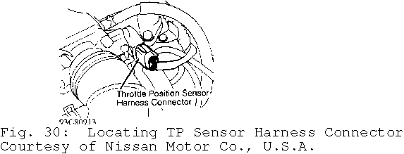
Fig. 31: DTC 43, Checking Power Supply Courtesy of Nissan Motor Co., U.S.A.
DTC 45, INJECTOR LEAK (CALIF.)
1) Clear Self-Learning Data
Start engine and bring to operating temperature. Stop engine and disconnect Mass Airflow (MA) sensor connector. Start and run engine for at least 30 seconds at 2000 RPM. Stop engine and connect MA sensor connector. Ensure DTC 12 is displayed in diagnostic test Mode
II. Erase self-diagnosis memory. Ensure DTC 55 is displayed in
diagnostic test Mode II.
2) Clear Self-Learning Data Using Consult Tester (J-38465)
Select SELF-LEARNING CONT in ACTIVE TEST mode. Clear self- learning control coefficient by touching CLEAR.
3) Perform Diagnostic Test Mode II (Self-Diagnostic Results)
If DTC 45 does not return, test is complete. If DTC 45 does
return, release fuel pressure. Remove injector assembly. DO NOT remove fuel hose or injector from injector gallery. Turn ignition on. Ensure fuel does not drip from injector(s). Repair or replace injector(s) as necessary. Perform FINAL CHECK in this article.