
�E -THEORY/OPERATION
�1993 Nissan Sentra
1993 ENGINE PERFORMANCE Nissan Theory & Operation
Altima, Maxima, NX, Pathfinder, Pickup, Quest, Sentra, 240SX, 300ZX
INTRODUCTION
This article covers basic description and operation of engine performance-related systems and components. Read this article before diagnosing vehicles or systems with which you are not completely familiar.
1993 TERMINOLOGY
Due to federal government requirements, manufacturers may use names and acronyms for systems and components different than those used in previous years. The following table will help eliminate confusion when dealing with these components and systems. Only relevant components and systems whose names have changed from current Nissan Motor Co. terminology have been listed. See REVISED TERMINOLOGY table.
REVISED TERMINOLOGY TABLE
�������������������������������������������������������������������������������������������������������������������������������
1992 & Earlier 1993
CHECK ENGINE Light ......... Malfunction Indicator Light (MIL) Camshaft Sensor ............... Camshaft Position (CMP) Sensor Crankshaft Angle Sensor ...... Cranksaft Position (CKP) Sensor DIS ................................. Electronic Ignition (EI) ECU .............................. Engine Control Module (ECM)
�������������������������������������������������������������������������������������������������������������������������������
AIR INDUCTION SYSTEM
POWER VALVE SYSTEM (MAXIMA)
The power valve system is designed to improve engine torque and power production by increasing or decreasing intake manifold induction volume under different driving conditions. A limited induction volume is desirable at low or medium speed under heavy load. This will increase intake velocity and improve atomizing of fuel and combustion efficiency. An increased induction volume is desirable under heavy load and high speed conditions.
Power valve system consists of power valve (built into intake manifold), diaphragm type power valve actuator, vacuum surge tank, power valve solenoid, one-way check valve and connecting vacuum hoses. See Fig. 1.
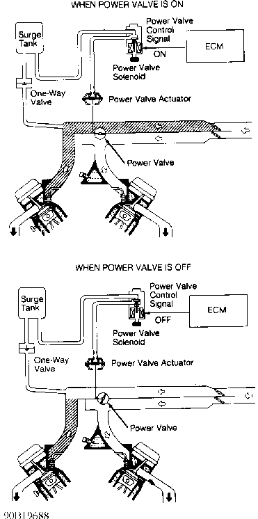
Fig. 1: Identifying Power Valve Operation (Maxima) Courtesy of Nissan Motor Co., U.S.A.
Power Valve
Valve is used to modify the induction passage of the power valve control system. It is set in the fully closed or fully open position by the power valve actuator. Power valve actuator is regulated by the ECM-controlled power valve solenoid. Vacuum for operating the actuator is stored in a surge tank.
Power Valve Solenoid
Power valve solenoid receives power from the Brown fusible link in the fuse box. Solenoid is energized when ECM provides a ground for solenoid through ECM terminal No. 8. For location and identification of ECM terminals, see L - WIRING DIAGRAMS article. When ECM activates power valve solenoid, vacuum from surge tank passes through solenoid to power valve actuator, pulling the power valve closed.
Surge Tank & One-Way Check Valve
When vehicle is running, manifold vacuum passes through the one-way check valve into the vacuum storage surge tank. Check valve holds vacuum in storage tank at a high level regardless of current manifold vacuum levels. This allows the power valve to remain fully closed under heavy engine loads when manifold vacuum is insufficient.
SWIRL COMBUSTION VALVE (SCV) SYSTEM (PICKUP 2.4L & 240SX)
The SCV system is designed to improve engine torque and power production by increasing or decreasing intake manifold induction volume under different driving conditions. A limited induction volume is desirable at low or medium speed under heavy load. This will increase intake velocity and improve atomizing of fuel and combustion efficiency. An increased induction volume is desirable under heavy load and high speed conditions.
SCV system consists of swirl control valve (built into intake manifold), diaphragm type swirl control valve actuator and swirl control valve solenoid.
Swirl Control Valve
Valve is used to modify the induction passage of the SCV system. It is set in the fully closed or fully open position by the swirl control valve actuator. Valve actuator is regulated by the ECM- controlled swirl control valve solenoid.
Swirl Control Valve Solenoid
Swirl control valve solenoid receives power from a 10-amp fuse in relay box. Solenoid is energized when ECM provides a ground for solenoid through ECM terminal No. 25 (terminal No. 12 on Pickup). For location and identification of ECM terminals, see appropriate L - WIRING DIAGRAMS article. When ECM activates solenoid, manifold vacuum passes through solenoid to swirl control valve actuator, pulling swirl control valve closed.
TURBOCHARGER (300ZX TURBO)
Turbocharger system uses twin turbochargers and twin air-toair intercoolers. A wastegate system is used to control maximum boost pressure. The wastegate is controlled by a solenoid valve.
Wastegate Control Solenoid Valve
Wastegate control solenoid valve changes vacuum source to wastegate valve actuator to achieve suitable turbo boost pressure. When detonation occurs, the solenoid valve turns off and opens wastegate valve, which lowers turbo boost pressure.
VALVE TIMING CONTROL SYSTEM (MAXIMA VE30DE, NX 1.6L,
SENTRA 1.6L & 300ZX)
Valve timing control system consists of intake camshaft pulley and advance/retard mechanism, valve timing control solenoid and oil control valve. See Fig. 2. Valve timing control is used to increase engine performance by advancing or retarding the intake camshaft.
Intake valve opening and closing points are controlled by the ECM according to engine operating conditions. This affects the overall torque curve by allowing more favorable torque applications at low-to-medium speeds. Inputs from the coolant temperature, throttle position and mass airflow sensors, as well as engine RPM and gear position, are used by ECM to determine operation.
Valve Timing Control Solenoid
Oil pressure, applied through valve timing control solenoid, is used to adjust camshaft pulley position. At idle or high speed, valve timing control solenoid is off, valve timing is retarded and valve overlap is decreased. At low-to-medium speed, valve timing control solenoid is on, valve timing is advanced and valve overlap is increased. This results in increased torque at lower engine RPM.
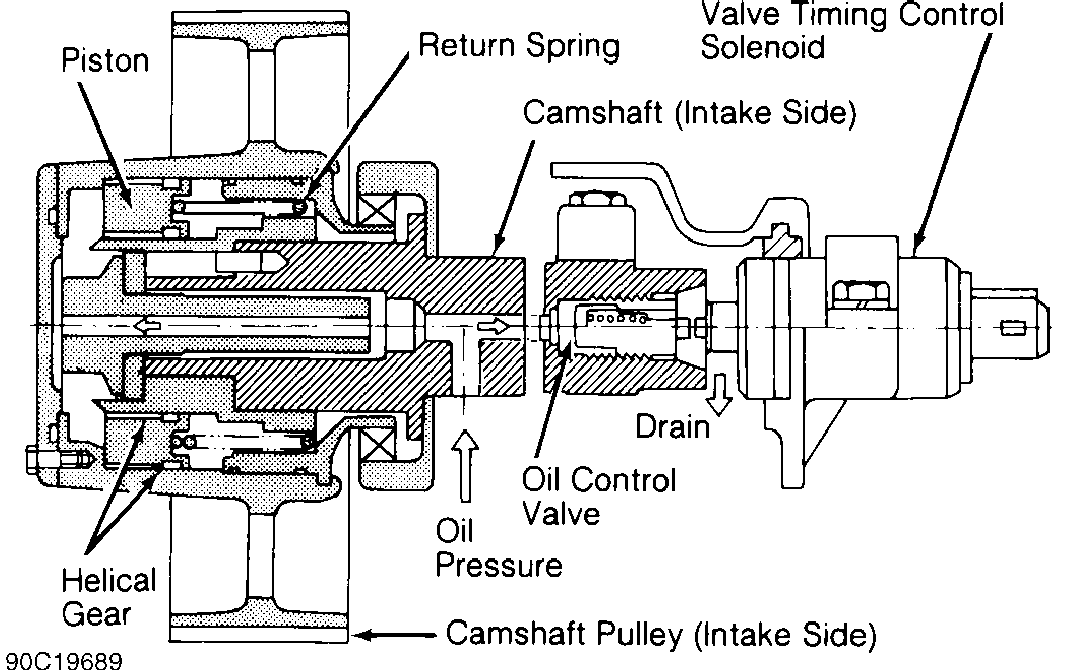
Fig. 2: Valve Timing Control System Component ID (300ZX Shown; Others Similar) Courtesy of Nissan Motor Co., U.S.A.
COMPUTERIZED ENGINE CONTROLS
The Electronic Concentrated Control System (ECCS) is a computerized emission, ignition, and fuel control system. A single Engine Control Module (ECM) uses input voltage signals received from various input components to control output.
ECM compares each input signal to the appropriate parameter preprogrammed in ECM and adjusts output voltage signals accordingly. This allows optimum vehicle performance under various conditions. Voltage to ECM and components requiring battery voltage is supplied by a safety relay and/or a main relay. Safety relay is used to prevent damage to ECM in the event of reverse polarity at the battery cables.
ENGINE CONTROL MODULE (ECM)
The ECM consists of a microcomputer, inspection lights (except Quest), diagnostic mode selector, connectors and wiring for voltage signal input, voltage signal output, and power supply. The unit is not serviceable and should not be opened. Inspection lights are provided on side of unit for self-diagnostic checks. The ECM contains memory and logic circuits, enabling it to interpret sensor inputs and control various engine systems. To locate ECM, see ECM LOCATIONS table.
ECM LOCATIONS TABLE
�������������������������������������������������������������������������������������������������������������������������
Application Location
Altima ............................... Under Center Console Maxima, NX & Sentra ................. Behind Center Console Pathfinder & Pickup .................. Under Passenger Seat Quest ...................... Behind Center Instrument Panel 240SX .................... Behind Passenger-Side Kick Panel 300ZX .................................... Behind Glove Box
�������������������������������������������������������������������������������������������������������������������������
NOTE: Components are grouped into 2 categories. The first category
is INPUT DEVICES, which are components that control or
produce voltage signals monitored by the ECM. The second
category is OUTPUT SIGNALS, which are components controlled
by the ECM.
INPUT DEVICES
Vehicles are equipped with different combinations of input devices. Not all devices are used on all models. Input signals include:
A/C Switch
Informs ECM when A/C system is on. ECM responds by increasing idle speed to improve idling and reduce emissions. During heavy engine load, ECM will also open the A/C clutch relay to disengage A/C clutch.
A/C Thermo Control Amplifier
Informs ECM of A/C system evaporator outlet temperature. Input helps determine cooling fan operation.
Air Temperature Sensor
The air temperature sensor is located in the air cleaner box. Sensor monitors temperature of incoming air. Sensor is a thermistor and increases (cold) or decreases (hot) its resistance in response to temperature changes. The air temperature sensor controls ignition timing when intake air temperature is extremely high to prevent engine knock (detonation).
Battery Voltage Compensation
Injector pulse width is directly affected by battery voltage. As battery voltage drops, so does injector pulse width, causing a lean air/fuel mixture. To compensate, ECM monitors battery voltage and increases injector pulse width if voltage drops. This monitored voltage is also used with other input values to calculate idle speed and is a factor for determining ignition timing.
Crankshaft Position (CKP) Sensor
The CKP sensor monitors engine speed and piston position. The CKP sensor, which is built into the distributor, has a rotor plate and a wave-forming circuit. The rotor plate has 360 small outer slits (one degree apart) to determine CKP and 4 (4-cylinder) or 6 (V6) larger inner signal slits, 90 (4-cylinder) or 60 (V6) degrees apart, to determine engine speed. See Fig. 6. The signal slit for cylinder No. 1 is the largest inner signal slit to allow ECM to determine TDC for cylinder No. 1.
When the signal rotor plate passes the space between the Light Emitting Diode (LED) and photo diode, the slits in the signal rotor plate alternately cut the light from LED to the photo diode. This causes a pulsating voltage, which is converted into an on-off pulse by the wave-forming circuit and sent to the ECM. ECM uses this signal to control fuel injection, ignition timing and other functions.
Engine Coolant Temperature (ECT) Sensor
ECT sensor is installed in the coolant inlet housing or intake manifold coolant passage. Sensor senses changes in temperature by monitoring the resistance of a thermistor. As temperature increases, thermistor resistance decreases.
Sensor sends temperature information to ECM for air/fuel mixture, timing and idle speed control. During warm-up from cold start, ECM increases fuel enrichment to maintain engine performance. As engine temperature increases, the ECM gradually decreases fuel enrichment until engine reaches normal operating temperature.
EGR Temperature Sensor (California Models)
EGR temperature sensor, located near EGR valve, detects temperature of exhaust gases passing through EGR valve. Sensor has a thermistor which changes its resistance value in response to changes in exhaust gas temperature. As temperature of exhaust gases increases, resistance of sensor decreases. ECM analyzes these changes in resistance and adjusts output voltage signals to EGR solenoid accordingly.
Fuel Temperature Sensor
Fuel temperature sensor is built into fuel rail. When fuel temperature is more than specified, ECM turns on Pressure Regulator Valve (PRV) control solenoid to increase fuel pressure.
Ignition Switch
ECM detects when ignition switch is in ON or START position. When ECM receives voltage signal for START position, it will actuate injectors and compute and initiate ignition timing sequence and other functions, including EGR control override during start-up.
Inhibitor Switch (A/T Models)
Switch is located on transmission/transaxle. Switch notifies ECM when transmission/transaxle is in Park or Neutral and signals ECM of increased engine load when vehicle is in gear. This signal is used to calculate required changes in idle speed, ignition timing and injector operation.
Knock Sensor (KS)
Basic ignition timing is preprogrammed. Detonation sensor detects engine knocking, converts knocking vibration into voltage signal and transmits signal to the ECM. Information is used by ECM to adjust ignition timing accordingly to eliminate detonation.
Mass Airflow Sensor
Mass airflow sensor is located in main air intake duct. The sensor uses a hot-wire type sensing element. Incoming air passing through the airflow sensor causes the hot wire to cool. As a result, ECM must apply additional current to maintain hot wire at the precalibrated temperature. The ECM measures airflow by monitoring the amount of additional current required to maintain hot wire at the precalibrated temperature.
If airflow sensor output current is outside normal operational range, a malfunction in airflow sensor is indicated. ECM will go to throttle position sensor for information on driving condition. During this period, ECM will limit engine speed to less than 2000 or 3000 RPM, depending on model. This will inform the driver that the vehicle is driving under fail-safe conditions and needs attention.
Since the hot wire is exposed to atmospheric contaminants, the ECM is programmed to clean the hot-wire each time the ignition is cycled off. This is accomplished by heating the hot wire to 1832 � F (1000 � C) for one second after ignition has been turned off for 5
seconds. This function will not occur if engine speed has not exceeded 1500 RPM, vehicle speed has not exceeded 12 MPH, engine has stalled with ignition on, or engine is overheated.
Neutral Switch (M/T Models)
Switch is located on transmission/transaxle. Switch notifies ECM when transmission/transaxle is in Neutral and signals ECM of increased load when vehicle is in gear. Information is used to calculate required changes in idle speed, ignition timing and injector operation.
Oxygen Sensor
Sensor monitors the amount of unburned oxygen in the exhaust gases. When heated in the presence of exhaust gases, sensor provides a voltage signal which is used to adjust air/fuel mixture to obtain optimum combustion. Two types of oxygen sensor are used: heated (3wires) and non-heated (one-wire). The heating circuit quickly brings sensor to operating temperature.
A rich exhaust gas mixture causes sensor voltage to drop; a lean exhaust gas mixture causes voltage to increase. The ECM monitors the return signal from sensor and adjusts the air/fuel mixture according to this return signal.
Power Steering Oil Pressure Switch
Switch is attached to the power steering high pressure line. Switch monitors the power steering load and sends signal to the ECM. When oil pressure exceeds a predetermined amount, ECM sends a voltage signal to idle speed control valve to increase idle speed.
Throttle Position (TP) Sensor & Idle Switch
The TP sensor has a potentiometer which varies output voltage in response to changes in throttle position. This information is relayed to ECM in form of an input voltage signal on the 3-terminal TP sensor harness. TP sensor also has the ability to inform ECM of the rate of changes taking place in throttle plate movement. TP sensor is attached to throttle body housing and is actuated by movement of the accelerator pedal.
The idle switch is an integral part of the TP sensor. Switch is closed at idle and open during all other conditions. Switch is used to inform the ECM when the throttle is closed for fuel-cut on deceleration. Switch also has a full throttle position used only on vehicles equipped with an automatic transmission control unit.
Vehicle Speed Sensor (VSS)
Provides ECM with vehicle speed signal. VSS consists of a reed switch installed in speedometer unit. Reed switch transforms vehicle speed into pulsed signal.
OUTPUT SIGNALS
Vehicles are equipped with different combinations of ECM- controlled components. Not all components listed below are used on every vehicle. For theory and operation on each output component, refer to the indicated system.
A/C Clutch See MISCELLANEOUS CONTROLS.
Air-Cut Valve See IDLE SPEED under FUEL SYSTEM.
Air Injection Valve (AIV) Control See AIR INJECTION under EMISSION SYSTEMS.
Air Regulator See IDLE SPEED under FUEL SYSTEM.
Mass Airflow Sensor Self-Cleaning See MASS AIRFLOW SENSOR under INPUT DEVICES.
Automatic Transmission/Transaxle Control Unit (ATCU)
See TRANSMISSION/TRANSAXLE CONTROLS under MISCELLANEOUS CONTROLS.
Auxiliary Air Control (AAC) Valve See IDLE SPEED under FUEL SYSTEM.
Canister Purge Control See FUEL EVAPORATION SYSTEM under EMISSION SYSTEMS.
Cooling Fan Motor See COOLING FAN under MISCELLANEOUS CONTROLS.
Cooling Fan Relay See COOLING FAN under MISCELLANEOUS CONTROLS.
Exhaust Gas Recirculation (EGR) Control
See EXHAUST GAS RECIRCULATION (EGR) SYSTEM under EMISSION SYSTEMS.
Fast Idle Control Device (FICD) Solenoid See IDLE SPEED under FUEL SYSTEM.
Fuel Injector See FUEL CONTROL under FUEL SYSTEM.
Fuel Pump Control Module (300ZX) See FUEL DELIVERY under FUEL SYSTEM.
Fuel Pump Relay See FUEL DELIVERY under FUEL SYSTEM.
Idle Speed Control See IDLE SPEED under FUEL SYSTEM.
Ignition Timing Control See IGNITION TIMING CONTROL SYSTEM under IGNITION SYSTEM.
Power Valve Solenoid See POWER VALVE SYSTEM (MAXIMA) under AIR INDUCTION SYSTEM.
Power Transistor & Ignition Coil(s) See DISTRIBUTOR IGNITION (DI) SYSTEM under IGNITION SYSTEM.
Pressure Regulator Control Solenoid See FUEL DELIVERY under FUEL SYSTEM.
Swirl Control Valve Solenoid
See SWIRL COMBUSTION VALVE (SCV) SYSTEM (PICKUP 2.4L & 240SX) under AIR INDUCTION SYSTEM.
Valve Timing Control
See VALVE TIMING CONTROL SYSTEM (MAXIMA VE30DE, NX 1.6L, SENTRA 1.6L & 300ZX) under AIR INDUCTION SYSTEM.
Wastegate Control Solenoid Valve
See TURBOCHARGER (300ZX TURBO) under AIR INDUCTION SYSTEM.
FUEL SYSTEM
FUEL DELIVERY
Fuel Pump
The electric in-tank fuel pump is turned on by the ECM. Fuel pump is activated when ECM supplies the missing voltage or ground signal through the fuel pump relay. Fuel pump will be energized by the ECM for up to 5 seconds when ignition is first turned on, during cranking and during running. Fuel pump will be de-energized about one second after engine stops.
Fuel Pump Control Module (300ZX)
When fuel pump relay is activated, battery voltage is directed through the relay to fuel pump control module and fuel pump. See FUEL PUMP RELAY (300ZX). The fuel pump control module adjusts the voltage supplied to fuel pump according to engine conditions. Fuel pump control module supplies about 14 volts to fuel pump under following conditions:
- *
- One second after ignition switch is turned to ON position.
- *
- During engine cranking.
- *
- Thirty seconds after engine starts at temperatures greater than
��
122 F (50 C). ��
- *
- Engine temperature is less than 50 F (10 C).
- *
- Engine is running under heavy load condition.
Under conditions other than those listed, fuel pump control module limits fuel pump voltage to about 8 volts.
Fuel Pump Relay (Except Maxima & 300ZX)
Fuel pump relay receives current from battery or from the ignition switch when switch is in the ON position. Relay is energized when a ground is supplied at ECM terminal No. 104. This causes relay contacts to close, delivering battery voltage to the in-tank fuel pump.
Fuel Pump Relay (Maxima)
On VG30E engine, fuel pump receives battery voltage through a 10-amp fuse. Ground circuit for fuel pump is provided directly from ECM during engine cranking. When vehicle is running, ground is provided through fuel pump relay. If ECM detects a fuel pump circuit failure, it will energize the fuel pump through a back-up circuit.
On VE30DE engine, the ECM operates the fuel pump for 5 seconds after ignition is turned on. The ECM controls the fuel pump relay, which in turn controls the fuel pump. If the ECM receives 120degree signal from crank angle sensor, it knows that engine is running and causes the fuel pump to remain on. If 120-degree signal from crank angle sensor is not received, ECM stops fuel pump operation.
Fuel Pump Relay (300ZX)
Fuel pump relay receives battery voltage through a fusible link. Ground circuit for fuel pump relay is provided through ECM. When fuel pump relay is activated, battery voltage is directed through relay to fuel pump control module and then fuel pump. See FUEL PUMP CONTROL MODULE (300ZX).
Fuel Pressure Regulator
Fuel is delivered to the injector from the in-tank electric fuel pump. Fuel pressure at the injector is regulated by the fuel
pressure regulator, located in the fuel return line between the injector and the fuel tank. The pressure regulator is a sealed unit divided into 2 chambers (fuel and spring) by a diaphragm. The fuel chamber receives fuel through the inlet side from the injector fuel rail. The spring chamber is connected to intake manifold vacuum.
A vacuum-operated diaphragm inside the regulator maintains fuel pressure at a specific range, taking into consideration changes in engine load. At idle, intake manifold vacuum is high, causing the diaphragm to be pulled down, allowing excessive fuel to be returned to the fuel tank. As the throttle is depressed, intake manifold vacuum decreases, allowing diaphragm regulator spring to overcome manifold vacuum, causing diaphragm to block fuel returning to fuel tank. This causes an increase in fuel pressure.
Pressure Regulator Control Solenoid
When the pressure regulator control solenoid is energized, vacuum to the fuel pressure regulator is blocked, causing fuel pressure to increase. ECM energizes the pressure regulator control solenoid for 30 seconds each time the vehicle is started. When coolant temperature is greater than 172 � F (78 � C) and engine speed is less than 2500 RPM or engine load is light, ECM will energize the pressure regulator control solenoid for up to 3 minutes. This improves hot engine start.
FUEL CONTROL
Feedback System
ECM calculates base injection pulse width by processing signals from the CKP sensor and mass airflow sensor. After receiving signals from sensors detecting engine conditions, ECM adds fuel enrichment (preprogrammed into the control unit) to the base injection width to obtain optimum fuel mixture for all operating conditions. Fuel enrichment is always available during warm-up, starting, off idle, heavy load and when engine temperature is great.
Fuel injection system incorporates mixture ratio feedback. It is designed to maintain a precise mixture ratio. Through input signals from the oxygen sensor, ECM can adjust air/fuel ratio to optimally control exhaust emissions and engine performance. This function takes place during closed loop operation. ECM continuously monitors itself to stay within an acceptable emissions output range. However, this feedback system can be overridden and will operate in open loop when one or more of the following conditions exist:
- *
- Starting.
- *
- Engine and/or oxygen sensor cold.
- *
- Driving at high speeds or under heavy load.
- *
- Idling.
- *
- Oxygen sensor monitors a too rich condition for over 10 seconds.
- *
- Fuel shutoff solenoid is activated.
- *
- Vehicle is decelerating.
- *
- EGR temperature sensor is malfunctioning.
Fuel Injector
The fuel injector is a small elaborate solenoid. The ECM sends a duration signal to the injector, which in turn opens to high pressure fuel supplied by the fuel pump.
Sequential Fuel Injection (SFI)
SFI vehicles can operate in one of 2 injection modes: simultaneous or sequential. In simultaneous injection mode, fuel is injected into all cylinders at same time. In sequential injection mode, injectors are triggered in spark plug firing order. Fuel injection operates in sequential mode under most conditions. Fuel
injection will shift from sequential to simultaneous mode under following conditions: when engine speed is less than 300 RPM, when engine temperature is less than 140 � F (60 � C), and during starting.
If mass airflow sensor malfunctions, ECM will enter fail-safe mode. In fail-safe mode, fuel injection is determined from internal default tables based on throttle position. During fail-safe mode, engine speed is limited to less than 2000 or 3000 RPM, depending on model. When the engine reaches this maximum RPM, it will not go faster, indicating the fail-safe system is in effect and vehicle needs servicing.
IDLE SPEED
Idle Speed Control
ECM controls engine idle speed according to engine operating conditions and component/model application. ECM will send a signal to adjust and compensate for idle speed under the following conditions (if applicable on system): from starting to 20 seconds after start, low battery voltage, headlights on, heater switch on, A/C switch on, rear defogger on, power steering oil pressure switch on, radiator fan switch on, during deceleration and when vehicle is moving at idle. ECM will also send voltage signal to one or more of the following components as applicable:
- *
- Altima, NX & Sentra - AAC Valve, IAC Valve, Fast Idle Control Device (FICD), Air Regulator
- *
- Maxima - AAC Valve, Air-Cut Valve
- *
- Pathfinder & Pickup - AAC Valve, Air Regulator (3.0L), Air Cut Valve
- *
- 240SX - AAC Valve, Air Regulator
- *
- 300ZX - AAC Valve, Fast Idle Control Device (FICD), Air Regulator
Auxiliary Air Control (AAC) Valve (Solenoid Type)
The ECM processes signals received from sensors to determine the optimum idle speed under varying engine conditions. The ECM senses engine condition and determines the best idle speed with regard to coolant temperature and transmission/transaxle gear position. ECM will then send an electrical on-off signal corresponding to the difference between actual and optimum idle speed. AAC solenoid then regulates the amount of by-passing air. ECM controls AAC solenoid by varying the electrical signal "on" time.
Auxiliary Air Control (AAC) Valve (Motor Type)
ECM processes signals received from sensors to determine optimum idle speed for various engine conditions. AAC valve is a stepper motor with 4 windings. Windings are energized to extend or retract AAC plunger to increase or decrease air by-passed around throttle plate. When plunger retracts, idle speed increases. When plunger extends, idle speed decreases. AAC valve is mounted on idle air adjusting unit. See Fig. 3.
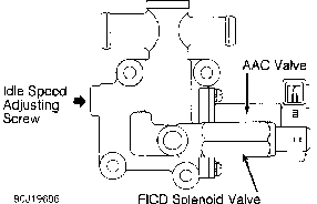
Fig. 3: Idle Air Adjusting Unit ID (300ZX Shown; Other Models Similar) Courtesy of Nissan Motor Co., U.S.A.
Air-Cut Valve
The air-cut valve is mounted under the Auxiliary Air Control (AAC) valve. Air-cut valve sensing unit is exposed to coolant flow. As coolant temperature gradually increases, the air-cut door will begin closing to limit maximum airflow through AAC, eliminating possible dieseling in the event of AAC failure.
Air Regulator
The air regulator provides an air by-pass when engine is cold for fast idle during warm-up. A bimetallic heater and rotary shutter valve control the rate of air by-pass. See Fig. 4. When the bimetallic heater and shutter are cold, air by-pass port is open. As engine starts and an electrical current is permitted to flow through the bimetallic heater, it warms up and closes the air by-pass port. The air regulator and fuel pump are both energized by the fuel pump relay.
Fast Idle Control Device (FICD) Solenoid
FICD increases the idle speed for a few seconds when vehicle is first started and when A/C compressor is engaged.
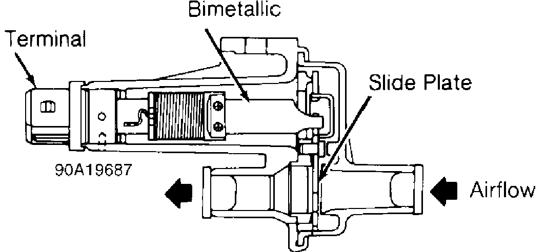
Fig. 4: Air Regulator ID (NX 1.6L, Pathfinder, Pickup 3.0L, Sentra 1.6L, 240SX & 300ZX) Courtesy of Nissan Motor Co., U.S.A.
IGNITION SYSTEM
NOTE: All models use a Light Emitting Diode (LED) Crankshaft Position (CKP) sensor. For additional information on operation, see INPUT DEVICES under COMPUTERIZED ENGINE CONTROLS.
ELECTRONIC IGNITION (EI) SYSTEM
The distributorless type ignition system uses one coil per cylinder. Individual coils are plugged directly onto spark plugs. See Fig. 5. A crank angle sensor (mounted on front of left exhaust camshaft) monitors engine speed and piston location. Signals created
by the crank angle sensor are sent to the ECM for processing. ECM then delivers ignition signals to the power transistor to control ignition by triggering the appropriate ignition coil. Power for ignition coils is supplied from ignition switch through the power transistor relay.
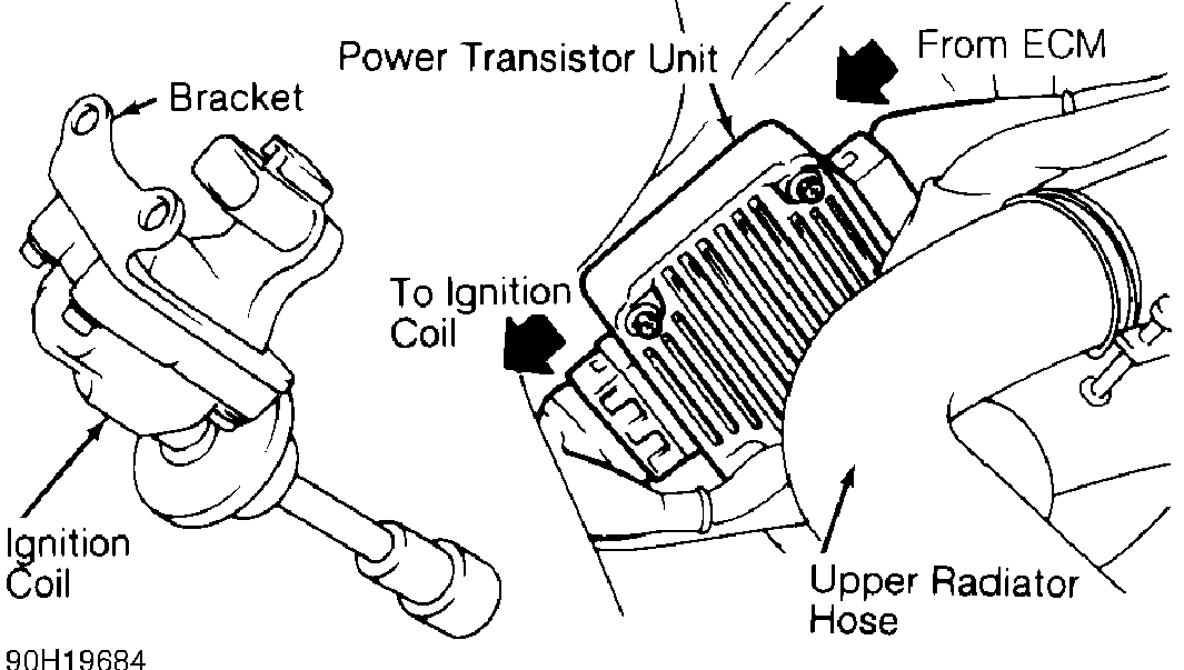
Fig. 5: Identifying Direct Ignition System (300ZX) Courtesy of Nissan Motor Co., U.S.A.
DISTRIBUTOR IGNITION (DI) SYSTEM
A crank angle sensor mounted inside the distributor monitors engine speed and piston location. See Fig. 6. Signals created by the crank angle sensor are sent to the ECM.
Power Transistor & Ignition Coil(s)
Power transistor uses ignition signals received from ECM to trigger ignition coil. Power for ignition coil(s) is supplied through the ignition switch.
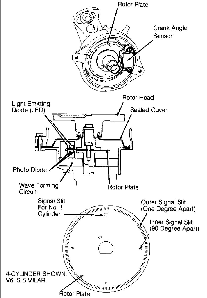
Fig. 6: Distributor & Crank Angle Sensor Component ID (Direct Ignition Crank Angle Sensor Is Similar) Courtesy of Nissan Motor Co., U.S.A.
IGNITION TIMING CONTROL SYSTEM
The ignition system controls ignition timing by matching vehicle operating conditions to preprogrammed timing advance and retard specifications. These parameters are stored in the ECM memory. The ECM uses input from the crank angle, coolant and various other sensors to determine advance requirements.
Ignition timing is controlled by the ECM according to engine operating conditions. Optimum ignition timing for various driving conditions is preprogrammed and stored in the ECM. ECM receives and processes electrical signals from various sensors to determine present driving conditions. ECM will then select optimum timing signal for the present conditions and send voltage signal to the power transistor to control timing advance and detonation retard operation (if equipped).
Ignition Timing Retard
See KNOCK SENSOR (KS) under INPUT DEVICES under COMPUTERIZED ENGINE CONTROLS.
EMISSION SYSTEMS
AIR INJECTION
Pulsed Secondary Air Injection (PAIR) System
The air injection system is designed to send secondary air to exhaust manifold in response to vacuum caused by exhaust system pulsation. When secondary air is injected into the exhaust manifold, continued burning of HC and CO in the exhaust system is allowed. Tailpipe emissions of hydrocarbons (HC) and carbon monoxide (CO) are reduced.
PAIR Solenoid
PAIR system operation is controlled by on/off switching of PAIR solenoid. ECM monitors engine operation and switches solenoid position depending on input received from various system sensors. PAIR solenoid will be activated by ECM when vehicle is in the following conditions:
�� �
* Idling or running at temperatures between 59 F (15 C) and 140 F
�
(60 C). ��
- *
- Idling at temperatures greater than 158 F (70 C).
- *
- Decelerating.
FUEL EVAPORATION SYSTEM
The fuel evaporation system is used to reduce emissions of hydrocarbons (HC) into the atmosphere. The system consists of a sealed fuel tank, vacuum relief filler cap, charcoal canister, purge control valve, fuel-check valve, canister purge and vacuum signal lines, and vapor vent lines. Fuel vapor from the sealed fuel tank is stored in the activated charcoal canister when the engine is not running. Fuel vapor is retained in the canister until purged by air drawn through the bottom of the canister to the intake manifold during engine operation.
When engine is running at idle, purge control valve is closed and only a small amount of stored vapor flows into the intake manifold through the constant purge orifice. As engine speed increases and the throttle vacuum rises higher, the purge control valve opens and vapors are drawn into the intake manifold through the main purge orifice and the constant purge orifice. See Figs. 7, 8 and 9.
Canister Purge Control Ported purge signal is regulated by the ECM using a
combination EGR and canister purge control solenoid.
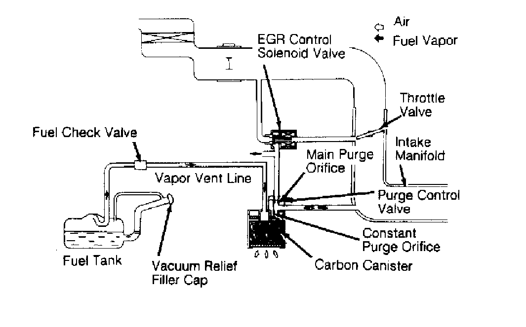
Fig. 7: Fuel Evaporation System ID (Altima & 240SX) Courtesy of Nissan Motor Co., U.S.A.
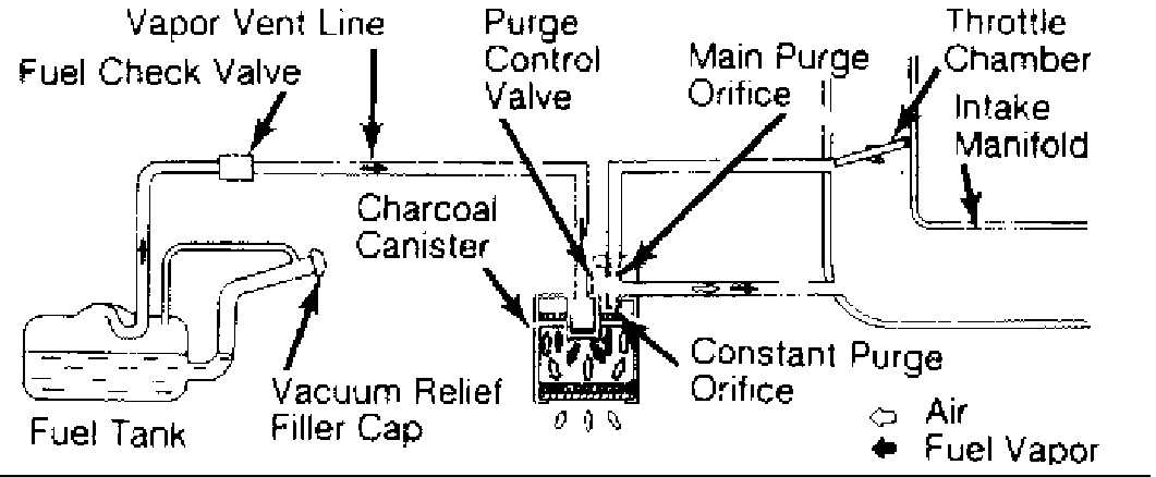
Fig. 8: Fuel Evaporation System ID (Maxima, Pathfinder, Pickup, Quest & 300ZX) Courtesy of Nissan Motor Co., U.S.A.
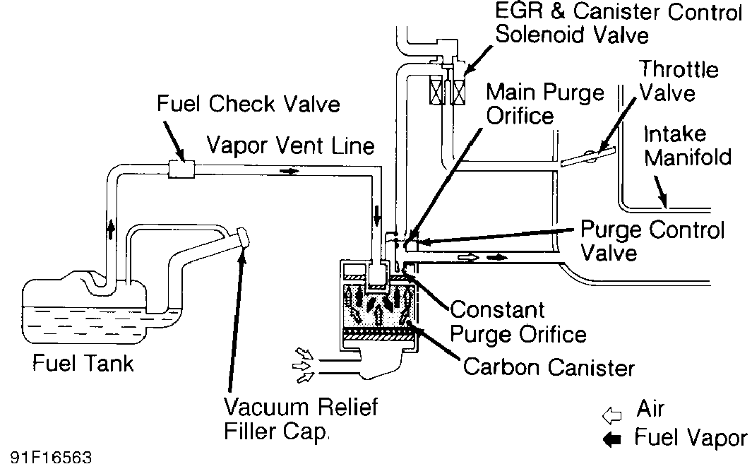
Fig. 9: Fuel Evaporation System ID (NX & Sentra) Courtesy of Nissan Motor Co., U.S.A.
EXHAUST GAS RECIRCULATION (EGR) SYSTEM
EGR Control
To reduce tailpipe emissions of NOx (oxides of nitrogen), an exhaust gas recirculation system is incorporated within the Electronic Concentrated Control System (ECCS). A portion of exhaust gases from the exhaust manifold is returned to the intake manifold and then the combustion chamber to be reburned. This is controlled by the EGR valve, EGR control solenoid valve and backpressure transducer (some models). EGR system does not operate under some or all of the following conditions:
- *
- Engine starting.
- *
- Throttle valve switch on.
- *
- Heavy engine load.
- *
- Low engine temperature.
- *
- High engine temperature at high engine speeds.
Under these conditions, ECM energizes the control solenoid to pull the plunger downward, allowing control vacuum to bleed off to atmosphere. California models are also equipped with EGR temperature sensor located near the EGR valve. This sensor is used to determine when EGR is actually occurring. If sensor indicates a low exhaust gas temperature when EGR action is commanded, ECM can determine if an EGR fault is present.
EGR Backpressure Transducer A backpressure transducer is installed in the EGR valve
vacuum hose. During periods of low exhaust backpressure, when EGR is not desirable, the transducer allows EGR vacuum signal to bleed off to atmosphere. When backpressure increases, internal diaphragm of transducer is lifted to block off vacuum bleed, allowing vacuum to operate EGR diaphragm.
SELF-DIAGNOSTIC SYSTEM
NOTE: For additional information, see G - TESTS W/ CODES article.
Except Quest
Two types of self-diagnostic systems are used: single LED and dual LED. Self-diagnostic system is located on the ECM. For system application, see SELF-DIAGNOSTIC SYSTEM table. For ECM locations, see ENGINE CONTROL MODULE (ECM) under COMPUTERIZED ENGINE CONTROLS.
Quest
Trouble codes are retrieved from ECM through MIL (CHECK ENGINE light) located on instrument panel. MIL is used with Diagnostic Test Connector (DTC). DTC is a 4-terminal connector located near the starter.
SELF-DIAGNOSTIC SYSTEM TABLE
���������������������������������������������������������������������������������������������������������������������
| Application | MIL | LED Colors (No.) | ||||||
|---|---|---|---|---|---|---|---|---|
| Altima, NX, Sentra, | ||||||||
| 240SX & 300ZX | ...... | Calif. & Fed. | ........... | Red (1) | ||||
| Maxima | ||||||||
| VE30DE | ............. | Calif. & Fed. | ........... | Red (1) | ||||
| VG30E | .............. | Calif. & Fed. | ... | Red & Green (2) | ||||
| Pathfinder | .......... | Calif. & Fed. | ... | Red & Green (2) | ||||
| Pickup | ||||||||
2.4L .................. Calif. ....... Red & Green (2)
3.0L ............... Calif. & Fed. ... Red & Green (2)
���������������������������������������������������������������������������������������������������������������������
SELF-DIAGNOSTIC SYSTEM (SINGLE LED - 2 MODES)
NOTE: Switching modes is not possible to when the engine is
running. ECM will switch back to MODE I when ignition is
turned off.
Self-diagnostic system will operate in one of 2 modes. On Quest,modes are changed by connecting and removing jumper wire between DTC terminals "A" and "B". On all other models, modes are manually changed using screwdriver through access port on ECM. To change mode, turn ignition on but DO NOT start engine. Turn screwdriver fully clockwise. Wait at least 2 seconds, then turn screwdriver fully counterclockwise. Inspection light will begin to flash.
Mode I (Malfunction Warning)
This is the normal vehicle operating mode in which engine must be running. On California models, if a malfunction occurs, Red LED and CHECK ENGINE light will glow, indicating an ECCS malfunction has occurred and a code has been stored. On Federal models, codes are stored and Red LED will glow only when ECM Central Processing Unit (CPU) malfunctions.
Mode II (Self-Diagnostics)
When mode is accessed, codes stored in ECM memory will be flashed by the CHECK ENGINE light and the Red LED on the side of the
ECM (if equipped). Long flashes (.6 second) represent the first digit of the code. Short flashes (.3 second) represent the second digit of the code. For example: 3 long flashes followed by 5 short flashes of the Red LED (or CHECK ENGINE light) would indicate a Code 35.
Mode II (Oxygen Sensor Monitor)
In this mode (engine running), both Red LED and CHECK ENGINE light are used to monitor air/fuel mixture feedback control. For results to be valid, vehicle must be in closed loop. In closed loop, Red LED will indicate if system is running rich (light off), lean (light on) or at ideal air/fuel ratio (blinking simultaneously with CHECK ENGINE light).
If 2 oxygen sensors are used, the left sensor is monitored first. To switch to right sensor, turn screwdriver fully clockwise with engine running. Wait at least 2 seconds, then turn screwdriver fully counterclockwise.
SELF-DIAGNOSTIC SYSTEM (DUAL LED - 5 MODES)
The self-diagnostic system is capable of detecting ECCS malfunctions and storing current and intermittent trouble codes. All codes are available for interpretation unless codes have been cleared or ignition has been cycled on-off 50 times since the malfunction last occurred.
Self-diagnostic system will be operated in one of 5 modes. Modes are manually changed using screwdriver through access port on ECM. To enter or change mode, turn screwdriver fully clockwise. Inspection lights will begin to flash. When desired mode has been entered, turn screwdriver fully counterclockwise. Red LED and Green LED perform different functions in different modes.
Mode I
This is the normal vehicle operating mode. Green LED will indicate loop status. If Green LED is not blinking, vehicle is in open loop or a fault exists with the oxygen sensor or sensor circuit. If Green LED is blinking, vehicle is in closed loop. If a malfunction occurs, Red LED and CHECK ENGINE light (if equipped) will glow, indicating an ECCS malfunction has occurred.
Mode II
Both Red LED and Green LED are used to monitor air/fuel mixture feedback control. Green LED will function as described in MODE
I. If vehicle is in open loop, Red LED and Green LED will remain on or off. In order for results to be valid, vehicle must be in closed loop. In closed loop, Red LED remains off if system is running rich, comes on if system is running lean and blinks simultaneously with Green LED if system is at the ideal air/fuel ratio.
Mode III
When mode is accessed, codes stored in ECM memory will be flashed by the Green LED and Red LED on the side of the ECM. Red LED will flash the first digit of the code; Green LED will flash the second digit of the code. For example: 3 flashes of the Red LED followed by 5 flashes of the Green LED indicates Code 35.
Mode IV
This mode is used for checking ECCS switch status. When the idle switch or starter switch is activated, the Red LED will come on and go off as the status changes. For vehicle speed sensor status, Green LED will remain off when vehicle speed is less than 12 MPH and come on when vehicle speed is greater than 12 MPH.
Mode V
This mode represents a real-time diagnostic test of the crank angle sensor, ignition signal, mass airflow output signal and fuel pump (Maxima). This mode is accessed for an in-bay running test of vehicle. Red and Green LEDs must be monitored carefully during this test; pay special attention to number of flashes before each pause.
The malfunction code will be displayed only once and will not be stored in memory. If Red LED blinks on and off uniformly, a fault in the crank angle sensor is indicated. If the Green LED flashes 2 times before a pause, it indicates a fault in the mass airflow sensor. If the Red LED blinks 3 times before a pause, a fault in the fuel pump circuit is indicated. If the Green LED blinks 4 times before a pause, a fault in the ignition signal is indicated.
CHECK ENGINE LIGHT
Except Pickup 2.4L (Federal)
All applicable vehicles are equipped with a CHECK ENGINE light on the instrument panel. Light comes on as a bulb check when the ignition switch is turned to the ON position. Light also comes on when systems related to the emission controls are malfunctioning during normal vehicle operation (MODE I). For additional information, see appropriate G - TESTS W/ CODES article.
MISCELLANEOUS CONTROLS
NOTE: Although not true engine performance-related systems, some
controlled devices may affect driveability if they
malfunction.
A/C CLUTCH
If A/C is turned on while engine is at idle, ECM will signal the Auxiliary Air Control (AAC) to increase idle speed. During hard acceleration, ECM cuts off the A/C power relay circuit to disengage A/C clutch for several seconds to aid acceleration.
COOLING FAN
Cooling Fan Motor
Cooling fan motor(s) is controlled by the ECM through the cooling fan relay(s). ECM will compensate idle speed when cooling fan is on.
Cooling Fan Relay
On models with multiple relays, one relay operates under normal or low speed operation and other operates under high speed or extra load conditions (A/C on). A third relay is sometimes used for operating the 2-speed cooling fan motor at high speed.
TRANSMISSION/TRANSAXLE CONTROLS
Some A/T models are equipped with an electronic Automatic Transmission/Transaxle Control Unit (ATCU). ATCU receives input signals from the ignition coil (RPM signal), idle switch (on-off signal), throttle sensor (variable signal) and full throttle switch (on-off signal). Based on these values, the ATCU calculates optimum timing and duration to energize shift solenoids, overrun clutch solenoid and lock-up solenoid. ATCU also indicates when Overdrive (OD) is engaged by illuminating the OD indicator light.