
�WIPER/WASHER SYSTEM
�1993 Nissan Sentra
1993 ACCESSORIES/SAFETY EQUIPMENT Nissan Wiper/Washer Systems
Sentra
DESCRIPTION & OPERATION
FRONT WIPER
System uses a 2-speed wiper motor with a park switch inside the motor housing. See Fig. 1. Intermittent (time delay) wiper function is controlled by:
* Wiper amplifier
Time control unit controls other time-delayed circuits such as clock, turn signals, hazard flasher and seat belt warning chime.
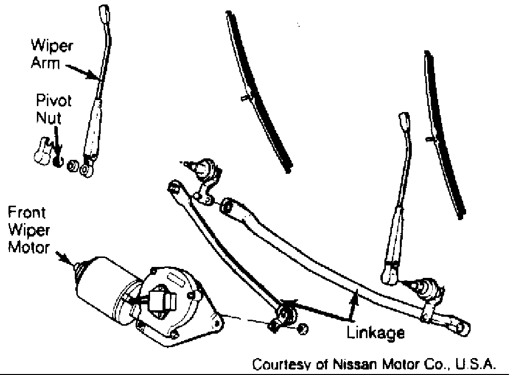
Fig. 1: Typical Front Wiper Components Courtesy of Nissan Motor Co., U.S.A.
WASHER
NOTE: Washer line between reservoir tank and nozzle contains a check valve that must be installed with arrow toward nozzle.
Front and rear washers use separate pumps. Both washer systems share a common reservoir.
ELECTRICAL COMPONENT LOCATIONS TABLE
�����������������������������������������������������������������������������������������������������������������������
| Component | Location | |
| Wiper Amplifier (Front) | .... | Integral Part Of Wiper Switch |
| On Combination Switch |
�����������������������������������������������������������������������������������������������������������������������
ADJUSTMENTS
WIPER ARM ADJUSTMENT
1) On front wipers, install wiper arm so distance from wiper blade centerline to bottom edge of glass is as specified in WIPER BLADE CLEARANCE table.
WIPER BLADE CLEARANCE TABLE
�����������������������������������������������������������������������������������������������������������������������
Application Clearance - In. (mm)
Front Left ................................... 1.0-1.4 (25-35) Right .................................. 0.8-1.2 (20-30) Rear ................................. 4.1-4.5 (105-115)
�����������������������������������������������������������������������������������������������������������������������
TESTING
TIME CONTROL UNIT
NOTE: Except for POWER & GROUND CIRCUITS test, the following procedures check only those Time Control Unit (TCU) functions that are related to wiper delay operation. During testing, leave TCU connector plugged in and backprobe TCU connector terminals with a Digital Volt-Ohmmeter (DVOM) unless specified otherwise.
Power & Ground Circuits
1) If time control function for ignition key warning or seat belt warning operates, TCU power and ground circuits are okay. If time control function for these systems is inoperative, turn ignition off.
2) Check continuity between ground and TCU connector terminal No. 15. See Fig. 2. If there is no continuity, repair ground circuit. If there is continuity, check voltage between TCU connector terminal No. 15 and terminal specified in TIME CONTROL UNIT POWER CIRCUIT TEST table. If voltage is not as specified, repair appropriate circuit.
TIME CONTROL UNIT POWER CIRCUIT TEST TABLE
�����������������������������������������������������������������������������������������������������������������������
Terminal Ignition Switch Number Position Volts
2 ........................ OFF ....................... 0 ACC ................. Battery ON .................. Battery
| 5 | ........................ | OFF | ....................... | 0 | ||
|---|---|---|---|---|---|---|
| ACC | ....................... | 0 | ||||
| ON | .................. | Battery | ||||
| 9 | ........................ | OFF | ................. | Battery | ||
| ACC | ................. | Battery | ||||
| ON | .................. | Battery | ||||
�����������������������������������������������������������������������������������������������������������������������
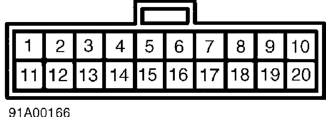
Fig. 2: Time Control Unit Connector Terminal ID Courtesy of Nissan Motor Co., U.S.A.
Intermittent Wiper Does Not Operate
1) Leave TCU harness connector connected. Turn ignition switch to ACC position. With wiper switch in INT or OFF position, measure voltage between TCU connector terminals No. 1 and 15. See Fig. 2.
2) With wiper switch in OFF position, about 12 volts should be present.
3) If voltage is not as specified, go to next step. If voltage is as specified, check wiper amplifier. See WIPER AMPLIFIER or WIPER RELAY under TESTING. If wiper amplifier or wiper relay is okay, repair wiring harness.
4) With wiper switch in INT or OFF position, measure voltage between TCU connector terminals No. 12 and 15. With wiper switch in OFF position, about 12 volts should be present. With wiper switch in INT position, no voltage should be present.
5) If voltages are as specified, replace TCU. If voltages are not as specified, check wiper switch. See STEERING COLUMN SWITCHES article in the ACCESSORIES/SAFETY EQUIPMENT section. If wiper switch is okay, repair wiring harness between TCU and wiper switch.
Intermittent Time Of Wiper Cannot Be Adjusted
1) Leave TCU harness connector connected. Turn ignition off. Measure resistance between TCU connector terminals No. 14 and 15 while turning intermittent wiper switch. See Fig. 2.
2) With switch in "S" position, resistance should be zero ohms. With switch in "L" position, resistance should be about 1000 ohms. If resistances are as specified, replace TCU. If resistances are not as specified, check intermittent wiper volume switch and wiring harness.
Wiper & Washer Activate Individually But Not In Combination
1) Leave TCU connector connected. Turn ignition switch to ACC position. Measure voltage between TCU connector terminals No. 13 and
15. See Fig. 2. With washer switch in OFF position, about 12 volts
should be present. With washer switch in ON position, no voltage should be present. If voltages are not as specified, repair wiring harness between TCU and wiper switch.
2) If voltages are as specified, measure voltage between TCU connector terminals No. 1 and 15 after operating washer switch. Voltmeter should indicate zero volts for about 3 seconds after washer has operated. If voltage is as specified, replace wiper relay. If voltage is not as specified, replace TCU.
WIPER AMPLIFIER
CAUTION: In the following procedure, carefully connect test leads to wiper amplifier connector to prevent damaging amplifier.
Disconnect amplifier connector. Connect test leads with test light(s) between 12-volt battery and amplifier connector terminals. See Fig. 3.
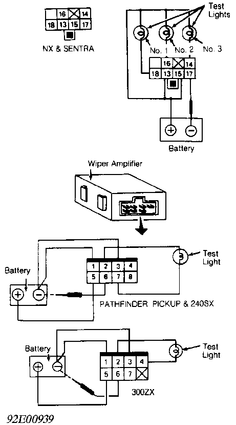
Fig. 3: Testing Wiper Amplifier Courtesy of Nissan Motor Co., U.S.A.
WIPER RELAY
Remove relay. There should be continuity between terminals No. 3 and 4, and no continuity between terminals No. 6 and 7. See Fig. 4. Apply battery voltage across terminals No. 1 and 2. There should now be no continuity between terminals No. 3 and 4, and continuity between terminals No. 6 and 7. If continuity is not as specified, replace relay.
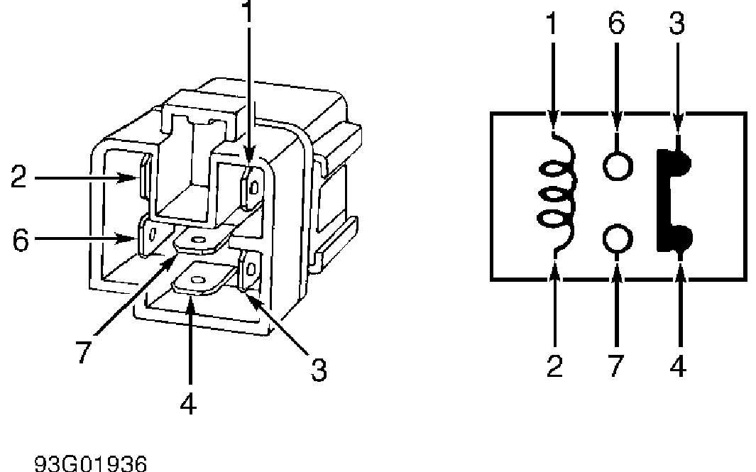
Fig. 4: Testing Wiper Relay Courtesy of Nissan Motor Co., U.S.A.
WIPER SWITCH
See STEERING COLUMN SWITCHES article in the ACCESSORIES/SAFETY EQUIPMENT section.
REMOVAL & INSTALLATION
WIPER MOTOR
NOTE: Before installing wiper arm(s), ensure wiper motor is in park position. See WIPER ARM ADJUSTMENT under ADJUSTMENTS.
TORQUE SPECIFICATIONS
WIPER ARM TORQUE SPECIFICATIONS TABLE
�����������������������������������������������������������������������������������������������������������������������
Application Ft. Lbs. (N.m) Front ...................................... 12-17 (16-23)
Rear ....................................... 10-13 (14-18)
�����������������������������������������������������������������������������������������������������������������������
WIRING DIAGRAMS
Proceed to chassis WIRING DIAGRAMS article in WIRING DIAGRAMS
section.